
In electrical engineering, ground or earth may be a reference point in an electrical circuit from which voltages are measured, a common return path for electric current, or a direct physical connection to the Earth.

A short circuit is an electrical circuit that allows a current to travel along an unintended path with no or very low electrical impedance. This results in an excessive current flowing through the circuit. The opposite of a short circuit is an open circuit, which is an infinite resistance between two nodes.
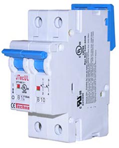
A circuit breaker is an electrical safety device designed to protect an electrical circuit from damage caused by overcurrent. Its basic function is to interrupt current flow to protect equipment and to prevent the risk of fire. Unlike a fuse, which operates once and then must be replaced, a circuit breaker can be reset to resume normal operation.

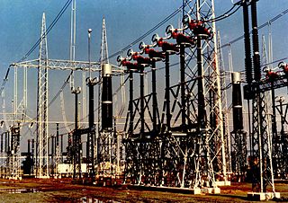
A substation is a part of an electrical generation, transmission, and distribution system. Substations transform voltage from high to low, or the reverse, or perform any of several other important functions. Between the generating station and consumer, electric power may flow through several substations at different voltage levels. A substation may include transformers to change voltage levels between high transmission voltages and lower distribution voltages, or at the interconnection of two different transmission voltages. They are a common component of the infrastructure. There are 55,000 substations in the United States.

A residual-current device (RCD), residual-current circuit breaker (RCCB) or ground fault circuit interrupter (GFCI) is an electrical safety device that interrupts an electrical circuit when the current passing through a conductor is not equal and opposite in both directions, therefore indicating an improper flow of current such as leakage current to ground or current flowing to another powered conductor. The device's purpose is to reduce the severity of injury caused by an electric shock. Injury from shock is limited to the time before the electrical circuit is interrupted, but the victim may also sustain further injury, e.g. by falling after receiving a shock. This type of circuit interrupter can not distinguish between current flowing though power carrying conductors that passes through a person from current that passes through electrical equipment and offer no protection when a person touches both conductors at the same time.

In electronics and electrical engineering, a fuse is an electrical safety device that operates to provide overcurrent protection of an electrical circuit. Its essential component is a metal wire or strip that melts when too much current flows through it, thereby stopping or interrupting the current. It is a sacrificial device; once a fuse has operated, it is an open circuit, and must be replaced or rewired, depending on its type.
Appliance classes specify measures to prevent dangerous contact voltages on unenergized parts, such as the metallic casing, of an electronic device. In the electrical appliance manufacturing industry, the following appliance classes are defined in IEC 61140 and used to differentiate between the protective-earth connection requirements of devices.

An arc-fault circuit interrupter (AFCI) or arc-fault detection device (AFDD) is a circuit breaker that breaks the circuit when it detects the electric arcs that are a signature of loose connections in home wiring. Loose connections, which can develop over time, can sometimes become hot enough to ignite house fires. An AFCI selectively distinguishes between a harmless arc, and a potentially dangerous arc.

In electrical engineering, ground and neutral are circuit conductors used in alternating current (AC) electrical systems. The neutral conductor returns current to the supply. To limit the effects of leakage current from higher-voltage systems, the neutral conductor is often connected to earth ground at the point of supply. A ground conductor is not intended to carry current for normal operation of the circuit, but instead connects exposed metallic components to earth ground. A ground conductor only carries significant current if there is a circuit fault that would otherwise energize exposed conductive parts and present a shock hazard. Circuit protection devices may detect a fault to a grounded metal enclosure and automatically de-energize the circuit, or may provide a warning of a ground fault.
Electrical wiring in the United Kingdom is commonly understood to be an electrical installation for operation by end users within domestic, commercial, industrial, and other buildings, and also in special installations and locations, such as marinas or caravan parks. It does not normally cover the transmission or distribution of electricity to them.

A current transformer (CT) is a type of transformer that is used to reduce or multiply an alternating current (AC). It produces a current in its secondary which is proportional to the current in its primary.

In electric power distribution, automatic circuit reclosers (ACRs) are a class of switchgear designed for use on overhead electricity distribution networks to detect and interrupt transient faults. Also known as reclosers or autoreclosers, ACRs are essentially rated circuit breakers with integrated current and voltage sensors and a protection relay, optimized for use as a protection asset. Commercial ACRs are governed by the IEC 62271-111/IEEE Std C37.60 and IEC 62271-200 standards. The three major classes of operating maximum voltage are 15.5 kV, 27 kV and 38 kV.
In an electric power system, a switchgear is composed of electrical disconnect switches, fuses or circuit breakers used to control, protect and isolate electrical equipment. Switchgear is used both to de-energize equipment to allow work to be done and to clear faults downstream. This type of equipment is directly linked to the reliability of the electricity supply.
An earthing system or grounding system (US) connects specific parts of an electric power system with the ground, typically the Earth's conductive surface, for safety and functional purposes. The choice of earthing system can affect the safety and electromagnetic compatibility of the installation. Regulations for earthing systems vary among countries, though most follow the recommendations of the International Electrotechnical Commission (IEC). Regulations may identify special cases for earthing in mines, in patient care areas, or in hazardous areas of industrial plants.
Power system protection is a branch of electrical power engineering that deals with the protection of electrical power systems from faults through the disconnection of faulted parts from the rest of the electrical network. The objective of a protection scheme is to keep the power system stable by isolating only the components that are under fault, whilst leaving as much of the network as possible in operation. The devices that are used to protect the power systems from faults are called protection devices.
In Electrical Power Systems and Industrial Automation, ANSI Device Numbers can be used to identify equipment and devices in a system such as relays, circuit breakers, or instruments. The device numbers are enumerated in ANSI/IEEE Standard C37.2 "Standard for Electrical Power System Device Function Numbers, Acronyms, and Contact Designations".
Breaking capacity or interrupting rating is the current that a fuse, circuit breaker, or other electrical apparatus is able to interrupt without being destroyed or causing an electric arc with unacceptable duration. The prospective short-circuit current that can occur under short circuit conditions should not exceed the rated breaking capacity of the apparatus, otherwise breaking of the current cannot be guaranteed. The current breaking capacity corresponds to a certain voltage, so an electrical apparatus may have more than one breaking capacity current, according to the actual operating voltage. Breaking current may be stated in terms of the total current or just in terms of the alternating-current (symmetrical) component. Since the time of opening of a fuse or switch is not coordinated with the reversal of the alternating current, in some circuits the total current may be offset and can be larger than the alternating current component by itself. A device may have different interrupting ratings for alternating and direct current.
In an electric power system, a fault or fault current is any abnormal electric current. For example, a short circuit is a fault in which a live wire touches a neutral or ground wire. An open-circuit fault occurs if a circuit is interrupted by a failure of a current-carrying wire or a blown fuse or circuit breaker. In three-phase systems, a fault may involve one or more phases and ground, or may occur only between phases. In a "ground fault" or "earth fault", current flows into the earth. The prospective short-circuit current of a predictable fault can be calculated for most situations. In power systems, protective devices can detect fault conditions and operate circuit breakers and other devices to limit the loss of service due to a failure.

In electrical engineering, isolated-phase bus (IPB), also known as phase-isolated bus (PIB) in some countries, is a method of construction for circuits carrying very large currents, typically between a generator and its step-up transformer in a steam or large hydroelectric power plant.

An electric power system is a network of electrical components deployed to supply, transfer, and use electric power. An example of a power system is the electrical grid that provides power to homes and industries within an extended area. The electrical grid can be broadly divided into the generators that supply the power, the transmission system that carries the power from the generating centers to the load centers, and the distribution system that feeds the power to nearby homes and industries.