Related Research Articles

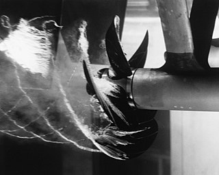
Cavitation is a phenomenon in which rapid changes of pressure in a liquid lead to the formation of small vapor-filled cavities in places where the pressure is relatively low.

A hydraulic jump is a phenomenon in the science of hydraulics which is frequently observed in open channel flow such as rivers and spillways. When liquid at high velocity discharges into a zone of lower velocity, a rather abrupt rise occurs in the liquid surface. The rapidly flowing liquid is abruptly slowed and increases in height, converting some of the flow's initial kinetic energy into an increase in potential energy, with some energy irreversibly lost through turbulence to heat. In an open channel flow, this manifests as the fast flow rapidly slowing and piling up on top of itself similar to how a shockwave forms.

A weir or low head dam is a barrier across the width of a river that alters the flow characteristics of water and usually results in a change in the height of the river level. They are also used to control the flow of water for outlets of lakes, ponds, and reservoirs. There are many weir designs, but commonly water flows freely over the top of the weir crest before cascading down to a lower level.

A spillway is a structure used to provide the controlled release of flows from a dam or levee into a downstream area, typically the riverbed of the dammed river itself. In the United Kingdom, they may be known as overflow channels. Spillways ensure that the water does not overflow and damage or destroy the dam.

Floodgates, also called stop gates, are adjustable gates used to control water flow in flood barriers, reservoir, river, stream, or levee systems. They may be designed to set spillway crest heights in dams, to adjust flow rates in sluices and canals, or they may be designed to stop water flow entirely as part of a levee or storm surge system. Since most of these devices operate by controlling the water surface elevation being stored or routed, they are also known as crest gates. In the case of flood bypass systems, floodgates sometimes are also used to lower the water levels in a main river or canal channels by allowing more water to flow into a flood bypass or detention basin when the main river or canal is approaching a flood stage.

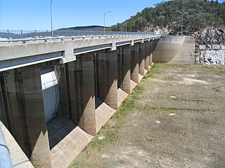
Copeton Dam is a major clay core and rock fill embankment dam with nine radial gates and a gated concrete chute spillway across the Gwydir River upstream of Bingara in the New England region of New South Wales, Australia. The dam's purpose includes environmental flows, hydro-electric power generation, irrigation, and water supply. The impounded reservoir is called Lake Copeton.

The Blowering Dam is a major ungated rock fill with clay core embankment dam with concrete chute spillway impounding a reservoir under the same name. It is located on the Tumut River upstream of Tumut in the Snowy Mountains region of New South Wales, Australia. Purposes for the dam include flood mitigation, hydro-power, irrigation, water supply and conservation. The dam is part of the Snowy Mountains Scheme, a vast hydroelectricity and irrigation complex constructed in south-east Australia between 1949 and 1974 and now run by Snowy Hydro.

The Contra Dam, commonly known as the Verzasca Dam and the Locarno Dam, is an arch dam on the Verzasca River in the Val Verzasca of Ticino, Switzerland. The dam creates Lago di Vogorno 2 km (1.2 mi) upstream of Lake Maggiore and supports the 105 MW Verzasca hydroelectric power station. It was constructed between 1961 and 1965 and starting shortly after its reservoir was filled, a series of earthquakes related to its water load occurred until 1971. The dam is owned and operated by Verzasca SA and is the fourth tallest in Switzerland.
The Temengor Dam or Temengor Hydro-Electric Project or Temengor Power Station is a dam in Gerik, Perak, Malaysia. It is located on Perak River about 200 km northeast of Ipoh. Construction of the dam impounded Temenggor Lake.
A flow splitter, in hydraulic engineering, is any device designed to break up the flow of water or nappe over a dam wall or weir. Flow splitters are used to reduce the likelihood of nappe vibration that might cause the failure of a dam wall by aerating the water flow. They are also used to restrict large flows of stormwater, in situations where a stormwater management device is designed only to treat small storms.
A drop structure, also known as a grade control, sill, or weir, is a manmade structure, typically small and built on minor streams, or as part of a dam's spillway, to pass water to a lower elevation while controlling the energy and velocity of the water as it passes over. Unlike most dams, drop structures are usually not built for water impoundment, diversion or raising the water level. Mostly built on watercourses with steep gradients, they serve other purposes such as water oxygenation and erosion prevention.

The Darbandikhan Dam is a multi-purpose embankment dam on the Diyala River in northern Sulaymaniyah Governorate, Iraq. It was constructed between 1956 and 1961. The purpose of the dam is irrigation, flood control, hydroelectric power production and recreation. Due to poor construction and neglect, the dam and its 249 MW power station have undergone several repairs over the years. A rehabilitation of the power station began in 2007 and was completed in 2013.
Hubert Chanson is a hydraulic engineering and applied fluid mechanics academic. Since 1990 he has worked at the University of Queensland.

Theodor Christoph Heinrich Rehbock was a German hydraulics engineer, and professor at the University of Karlsruhe.

A stepped spillway is a spillway with steps on the spillway chute to assist in the dissipation of the kinetic energy of the descending water. This eliminates or reduces the need for an additional energy dissipator, such as a body of water, at the end of the spillway downstream.

Aldeadávila Dam is a concrete arch-gravity dam on the Duero River on the border between Spain and Portugal. The Duero River forms the international boundary between Portugal and Spain. The nearest Spanish town is Aldeadávila de la Ribera in the Province of Salamanca, about 11.3 kilometres (7.0 mi) to the east. The nearest Portuguese town is Fornos in Bragança District, about 8 kilometres (5.0 mi) to the southwest. The Portuguese side of the river around the dam site lies within the International Duero Natural Park.

The Boyabat Dam is a concrete gravity dam on the Kızılırmak River bordering Sinop and Samsun Provinces, Turkey. It is 8 km (5 mi) southwest of Durağan and 24 km (15 mi) southeast of Boyabat. Construction began in 2008 and the dam and power plant were completed in December 2012. Its primary purpose is to generate hydroelectric power. The dam's power plant has an installed capacity of 513 MW.
Open channel spillways are dam spillways that utilize the principles of open-channel flow to convey impounded water in order to prevent dam failure. They can function as principal spillways, emergency spillways, or both. They can be located on the dam itself or on a natural grade in the vicinity of the dam.
In hydraulic engineering, air bubble entrainment is defined as the entrapment of air bubbles and pockets that are advected within the turbulent flow. The entrainment of air packets can be localised or continuous along the air–water interface. Examples of localised aeration include air entrainment by plunging water jet and at hydraulic jump. Bubbles are entrained locally at the intersection of the impinging jet with the surrounding waters. The intersecting perimeter is a singularity in terms of both air entrainment and momentum exchange, and the air is entrapped at the discontinuity between the impinging jet flow and the receiving pool of water. Interfacial aeration is defined as the air entrainment process along an air–water interface, usually parallel to the flow direction.

In February 2017, Oroville Dam's main and emergency spillways were damaged, prompting the evacuation of more than 180,000 people living downstream along the Feather River and the relocation of a fish hatchery.
References
- ↑ "Water and Wastewater Terms". Sacramento State (Office of Water Programs). Retrieved 21 April 2018.
- ↑ "What is the difference between a dam, a weir and a barrage?". GreenBug Energy Inc. Retrieved 21 April 2018.
- ↑ Chanson, Hurbert (1 January 1994). "Hydraulics of Nappe Flow Regime above Stepped Chutes and Spillways" (PDF). CE36 (1): 69–76. Retrieved 21 April 2018.Cite journal requires
|journal=(help) - ↑ Lodomez, Maurine (June 1, 2016). "Frequencies of Nappe Vibration for Free-overfall Structures" . Retrieved 21 April 2018.Cite journal requires
|journal=(help) - ↑ Chanson, Hurbert. "Design of Spillway Aeration Devices to prevent Cavitation Damage on Chutes and Spillways". The University of Queensland, School of Civil Engineering. Retrieved 21 April 2018.
- ↑ "Weirs". Code Cogs. Retrieved 21 April 2018.
- ↑ "Free Nappe". Meteorology Glossary American Meteorological Society. Retrieved 21 April 2018.
- ↑ Sawhney, G.S. (2011). Fundamentals of Fluid Mechanics (2 ed.). IK International Pvt Ltd. p. 411. ISBN 9789380578859 . Retrieved 21 April 2018.
- ↑ Thandaveswara, B.S. "Flow Over Weirs" (PDF). Hydraulics. Retrieved 21 April 2018.
- ↑ "Energy of Moving Water" (PDF). The Need Project (Student Guide): 14. 2013–2014. Retrieved 21 April 2018.
- ↑ Kharagpur. "Spillways and Energy Dissipators Version 2" (PDF). Hydraulic Structures for Flow Diversion and Storage (2): 4–11. Retrieved 21 April 2018.
- ↑ "Energy of Moving Water" (PDF). The Need Project (Student Guide): 14. 2013–2014. Retrieved 21 April 2018.
- ↑ Kharagpur. "Spillways and Energy Dissipators Version 2" (PDF). Hydraulic Structures for Flow Diversion and Storage (2): 4–11. Retrieved 21 April 2018.
- ↑ Naudascher, Eduard; Rockwell, Donald (2012). Flow-induced Vibrations: an Engineering Guide. Courier Corporation. pp. 2–21. ISBN 978-9054101314 . Retrieved 21 April 2018.
- ↑ Crookston, B.M.; Tullis, B.P. (9 October 2012). "Downloaded 435 times Technical Papers Hydraulic Design and Analysis of Labyrinth Weirs. II: Nappe Aeration, Instability, and Vibration". Journal of Irrigation and Drainage Engineering. 139 (5): 371–377. doi:10.1061/(asce)ir.1943-4774.0000553.
- ↑ Helmholtz, Hermann von. "Hydraulic design and analysis of labyrinth weirs. II: Nappe aeration, instability, and vibration". Journal of Irrigation and Drainage Engineering. 36 (4): 371–377.
- ↑ Falvey, Henry (1990). "Cavitation in chutes and spillways". US Department of the Interior, Bureau of Reclamation (42): 2–8. Retrieved 21 April 2018.
- ↑ Falvey, Henry (April 1990). "Cavitation in chutes and spillways". US Department of the Interior, Bureau of Reclamation (42): 29–35. Retrieved 21 April 2018.
- ↑ Chanson, Hubert (1994-01-01). "Hydraulics of Nappe Flow Regime above Stepped Chutes and Spillways". Australian Civil/Structural Engineering Transactions. CE36 (1): 69–76. Retrieved 21 April 2018.