
Geotechnical engineering is the branch of civil engineering concerned with the engineering behavior of earth materials. It uses the principles of soil mechanics and rock mechanics for the solution of its respective engineering problems. It also relies on knowledge of geology, hydrology, geophysics, and other related sciences. Geotechnical (rock) engineering is a subdiscipline of geological engineering.

In continuum mechanics, stress is a physical quantity, one of the standard mechanical quantities. It is a quantity that describes the magnitude of forces that cause deformation. Stress is defined as force per unit area. When an object is pulled apart by a force it will cause elongation which is also known as deformation, like the stretching of an elastic band, it is called tensile stress. But, when the forces result in the compression of an object, it is called compressive stress. It results when forces like tension or compression act on a body. The greater this force and the smaller the cross-sectional area of the body on which it acts, the greater the stress. Therefore, stress is measured in newton per square meter (N/m2) or pascal (Pa).
Stress–strain analysis is an engineering discipline that uses many methods to determine the stresses and strains in materials and structures subjected to forces. In continuum mechanics, stress is a physical quantity that expresses the internal forces that neighboring particles of a continuous material exert on each other, while strain is the measure of the deformation of the material.

In applied mechanics, bending characterizes the behavior of a slender structural element subjected to an external load applied perpendicularly to a longitudinal axis of the element.

Soil mechanics is a branch of soil physics and applied mechanics that describes the behavior of soils. It differs from fluid mechanics and solid mechanics in the sense that soils consist of a heterogeneous mixture of fluids and particles but soil may also contain organic solids and other matter. Along with rock mechanics, soil mechanics provides the theoretical basis for analysis in geotechnical engineering, a subdiscipline of civil engineering, and engineering geology, a subdiscipline of geology. Soil mechanics is used to analyze the deformations of and flow of fluids within natural and man-made structures that are supported on or made of soil, or structures that are buried in soils. Example applications are building and bridge foundations, retaining walls, dams, and buried pipeline systems. Principles of soil mechanics are also used in related disciplines such as geophysical engineering, coastal engineering, agricultural engineering, hydrology and soil physics.
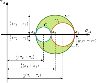
Mohr's circle is a two-dimensional graphical representation of the transformation law for the Cauchy stress tensor.

Euler–Bernoulli beam theory is a simplification of the linear theory of elasticity which provides a means of calculating the load-carrying and deflection characteristics of beams. It covers the case corresponding to small deflections of a beam that is subjected to lateral loads only. By ignoring the effects of shear deformation and rotatory inertia, it is thus a special case of Timoshenko–Ehrenfest beam theory. It was first enunciated circa 1750, but was not applied on a large scale until the development of the Eiffel Tower and the Ferris wheel in the late 19th century. Following these successful demonstrations, it quickly became a cornerstone of engineering and an enabler of the Second Industrial Revolution.

The effective stress can be defined as the stress, depending on the applied tension and pore pressure , which controls the strain or strength behaviour of soil and rock for whatever pore pressure value or, in other terms, the stress which applied over a dry porous body provides the same strain or strength behaviour which is observed at ≠ 0. In the case of granular media it can be viewed as a force that keeps a collection of particles rigid. Usually this applies to sand, soil, or gravel, as well as every kind of rock and several other porous materials such as concrete, metal powders, biological tissues etc. The usefulness of an appropriate ESP formulation consists in allowing to assess the behaviour of a porous body for whatever pore pressure value on the basis of experiments involving dry samples.
Soil consolidation refers to the mechanical process by which soil changes volume gradually in response to a change in pressure. This happens because soil is a two-phase material, comprising soil grains and pore fluid, usually groundwater. When soil saturated with water is subjected to an increase in pressure, the high volumetric stiffness of water compared to the soil matrix means that the water initially absorbs all the change in pressure without changing volume, creating excess pore water pressure. As water diffuses away from regions of high pressure due to seepage, the soil matrix gradually takes up the pressure change and shrinks in volume. The theoretical framework of consolidation is therefore closely related to the diffusion equation, the concept of effective stress, and hydraulic conductivity.
In geotechnical engineering, bearing capacity is the capacity of soil to support the loads applied to the ground. The bearing capacity of soil is the maximum average contact pressure between the foundation and the soil which should not produce shear failure in the soil. Ultimate bearing capacity is the theoretical maximum pressure which can be supported without failure; allowable bearing capacity is the ultimate bearing capacity divided by a factor of safety. Sometimes, on soft soil sites, large settlements may occur under loaded foundations without actual shear failure occurring; in such cases, the allowable bearing capacity is based on the maximum allowable settlement.
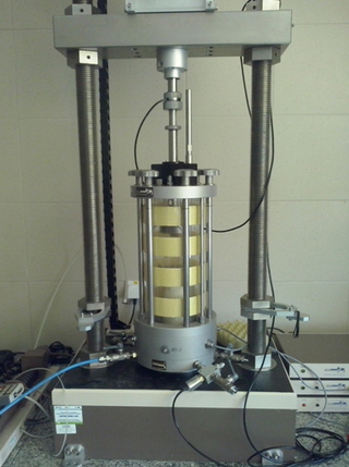
A triaxial shear test is a common method to measure the mechanical properties of many deformable solids, especially soil and rock, and other granular materials or powders. There are several variations on the test.

Lateral earth pressure is the pressure that soil exerts in the horizontal direction. The lateral earth pressure is important because it affects the consolidation behavior and strength of the soil and because it is considered in the design of geotechnical engineering structures such as retaining walls, basements, tunnels, deep foundations and braced excavations.
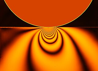
Contact mechanics is the study of the deformation of solids that touch each other at one or more points. A central distinction in contact mechanics is between stresses acting perpendicular to the contacting bodies' surfaces and frictional stresses acting tangentially between the surfaces. Normal contact mechanics or frictionless contact mechanics focuses on normal stresses caused by applied normal forces and by the adhesion present on surfaces in close contact, even if they are clean and dry. Frictional contact mechanics emphasizes the effect of friction forces.

Shear strength is a term used in soil mechanics to describe the magnitude of the shear stress that a soil can sustain. The shear resistance of soil is a result of friction and interlocking of particles, and possibly cementation or bonding of particle contacts. Due to interlocking, particulate material may expand or contract in volume as it is subject to shear strains. If soil expands its volume, the density of particles will decrease and the strength will decrease; in this case, the peak strength would be followed by a reduction of shear stress. The stress-strain relationship levels off when the material stops expanding or contracting, and when interparticle bonds are broken. The theoretical state at which the shear stress and density remain constant while the shear strain increases may be called the critical state, steady state, or residual strength.

Critical state soil mechanics is the area of soil mechanics that encompasses the conceptual models that represent the mechanical behavior of saturated remolded soils based on the Critical State concept.

Structural engineering depends upon a detailed knowledge of loads, physics and materials to understand and predict how structures support and resist self-weight and imposed loads. To apply the knowledge successfully structural engineers will need a detailed knowledge of mathematics and of relevant empirical and theoretical design codes. They will also need to know about the corrosion resistance of the materials and structures, especially when those structures are exposed to the external environment.
Preconsolidation pressure is the maximum effective vertical overburden stress that a particular soil sample has sustained in the past. This quantity is important in geotechnical engineering, particularly for finding the expected settlement of foundations and embankments. Alternative names for the preconsolidation pressure are preconsolidation stress, pre-compression stress, pre-compaction stress, and preload stress. A soil is called overconsolidated if the current effective stress acting on the soil is less than the historical maximum.
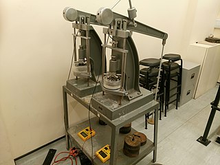
An oedometer test is a kind of geotechnical investigation performed in geotechnical engineering that measures a soil's consolidation properties. Oedometer tests are performed by applying different loads to a soil sample and measuring the deformation response. The results from these tests are used to predict how a soil in the field will deform in response to a change in effective stress.

Geotechnical centrifuge modeling is a technique for testing physical scale models of geotechnical engineering systems such as natural and man-made slopes and earth retaining structures and building or bridge foundations.
Stress distribution in soil is a function of the type of soil, the relative rigidity of the soil and the footing, and the depth of foundation at level of contact between footing and soil.The estimation of vertical stresses at any point in a soil mass due to external loading is essential to the prediction of settlements of buildings, bridges and pressure.