Instrumentation is a collective term for measuring instruments that are used for indicating, measuring and recording physical quantities. The term has its origins in the art and science of scientific instrument-making.
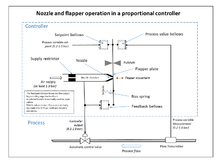
A proportional–integral–derivative controller is a control loop mechanism employing feedback that is widely used in industrial control systems and a variety of other applications requiring continuously modulated control. A PID controller continuously calculates an error value as the difference between a desired setpoint (SP) and a measured process variable (PV) and applies a correction based on proportional, integral, and derivative terms, hence the name.
An actuator is a component of a machine that is responsible for moving and controlling a mechanism or system, for example by opening a valve. In simple terms, it is a "mover".

A check valve, non-return valve, reflux valve, retention valve, foot valve, or one-way valve is a valve that normally allows fluid to flow through it in only one direction.
Fluid power is the use of fluids under pressure to generate, control, and transmit power. Fluid power is conventionally subdivided into hydraulics and pneumatics. Although steam is also a fluid, steam power is usually classified separately from fluid power. Compressed-air and water-pressure systems were once used to transmit power from a central source to industrial users over extended geographic areas; fluid power systems today are usually within a single building or mobile machine.
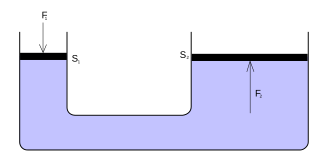
A hydraulic accumulator is a pressure storage reservoir in which an incompressible hydraulic fluid is held under pressure that is applied by an external source of mechanical energy. The external source can be an engine, a spring, a raised weight, or a compressed gas. An accumulator enables a hydraulic system to cope with extremes of demand using a less powerful pump, to respond more quickly to a temporary demand, and to smooth out pulsations. It is a type of energy storage device.

The J-2 is a liquid-fuel cryogenic rocket engine used on NASA's Saturn IB and Saturn V launch vehicles. Built in the U.S. by Rocketdyne, the J-2 burned cryogenic liquid hydrogen (LH2) and liquid oxygen (LOX) propellants, with each engine producing 1,033.1 kN (232,250 lbf) of thrust in vacuum. The engine's preliminary design dates back to recommendations of the 1959 Silverstein Committee. Rocketdyne won approval to develop the J-2 in June 1960 and the first flight, AS-201, occurred on 26 February 1966. The J-2 underwent several minor upgrades over its operational history to improve the engine's performance, with two major upgrade programs, the de Laval nozzle-type J-2S and aerospike-type J-2T, which were cancelled after the conclusion of the Apollo program.
A flow control valve regulates the flow or pressure of a fluid. Control valves normally respond to signals generated by independent devices such as flow meters or temperature gauges.

Fluidics, or fluidic logic, is the use of a fluid to perform analog or digital operations similar to those performed with electronics.

Hydraulic machines use liquid fluid power to perform work. Heavy construction vehicles are a common example. In this type of machine, hydraulic fluid is pumped to various hydraulic motors and hydraulic cylinders throughout the machine and becomes pressurized according to the resistance present. The fluid is controlled directly or automatically by control valves and distributed through hoses, tubes, or pipes.

Motion control is a sub-field of automation, encompassing the systems or sub-systems involved in moving parts of machines in a controlled manner. Motion control systems are extensively used in a variety of fields for automation purposes, including precision engineering, micromanufacturing, biotechnology, and nanotechnology. The main components involved typically include a motion controller, an energy amplifier, and one or more prime movers or actuators. Motion control may be open loop or closed loop. In open loop systems, the controller sends a command through the amplifier to the prime mover or actuator, and does not know if the desired motion was actually achieved. Typical systems include stepper motor or fan control. For tighter control with more precision, a measuring device may be added to the system. When the measurement is converted to a signal that is sent back to the controller, and the controller compensates for any error, it becomes a Closed loop System.
Hydropneumatic devices such as hydropneumatic accumulators or pulsation dampeners are devices which prevent, but do not absorb, alleviate, arrest, attenuate, or suppress a shock that already exists, meaning that these devices prevent the creation of a shock wave at an otherwise earlier stage. These can include pulsation dampeners, hydropneumatic accumulators, water hammer preventers, water hammer arrestors, and other things.
A control valve is a valve used to control fluid flow by varying the size of the flow passage as directed by a signal from a controller. This enables the direct control of flow rate and the consequential control of process quantities such as pressure, temperature, and liquid level.

A valve actuator is the mechanism for opening and closing a valve. Manually operated valves require someone in attendance to adjust them using a direct or geared mechanism attached to the valve stem. Power-operated actuators, using gas pressure, hydraulic pressure or electricity, allow a valve to be adjusted remotely, or allow rapid operation of large valves. Power-operated valve actuators may be the final elements of an automatic control loop which automatically regulates some flow, level or other process. Actuators may be only to open and close the valve, or may allow intermediate positioning; some valve actuators include switches or other ways to remotely indicate the position of the valve.
A shutdown valve is an actuated valve designed to stop the flow of a hazardous fluid upon the detection of a dangerous event. This provides protection against possible harm to people, equipment or the environment. Shutdown valves form part of a safety instrumented system. The process of providing automated safety protection upon the detection of a hazardous event is called functional safety.

A positive displacement meter is a type of flow meter that requires fluid to mechanically displace components in the meter in order for flow measurement. Positive displacement (PD) flow meters measure the volumetric flow rate of a moving fluid or gas by dividing the media into fixed, metered volumes. A basic analogy would be holding a bucket below a tap, filling it to a set level, then quickly replacing it with another bucket and timing the rate at which the buckets are filled. With appropriate pressure and temperature compensation, the mass flow rate can be accurately determined.
A flow limiter or flow restrictor is a device to restrict the flow of a fluid, in general a gas or a liquid. Some designs use single stage or multi-stage orifice plates to handle high and low flow rates. Flow limiters are often used in manufacturing plants as well as households. Safety is usually the main purpose of using a flow limiter. An example is manufacturing facilities and laboratories using flow limiters to prevent injury or death from noxious gases that are in use. The flow limiter prevents gases from causing injury or death by reducing its cross-sectional area where gas flows.
An electrohydraulic servo valve (EHSV) is an electrically-operated valve that controls how hydraulic fluid is sent to an actuator. Servo valves are often used to control powerful hydraulic cylinders with a very small electrical signal. Servo valves can provide precise control of position, velocity, pressure, and force with good post-movement damping characteristics.

Instrumentation is used to monitor and control the process plant in the oil, gas and petrochemical industries. Instrumentation ensures that the plant operates within defined parameters to produce materials of consistent quality and within the required specifications. It also ensures that the plant is operated safely and acts to correct out of tolerance operation and to automatically shut down the plant to prevent hazardous conditions from occurring. Instrumentation comprises sensor elements, signal transmitters, controllers, indicators and alarms, actuated valves, logic circuits and operator interfaces.
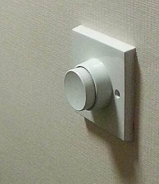
The first automatic timer, the dashpot timer has been used in many different machines and has many variations. Pneumatic, hydraulic-action, and mercury displacement timers. Being used in a variety of things such as printing presses, motors, and even irrigation systems, the dashpot timer has seen many applications. Even in modern times with electrical and digital timers, these old mechanical timers are still in use due to their simplicity and ability to function in tough environments.