P-cycle protection

Last updated

The p-Cycle protection scheme is a technique to protect a mesh network from a failure of a link, with the benefits of ring like recovery speed and mesh-like capacity efficiency, similar to that of a shared backup path protection (SBPP). p-Cycle protection was invented in late 1990s, with research and development done mostly by Wayne D. Grover, and D. Stamatelakis. [1] [2]

Contents

Overview of the p-Cycle

In Transport communication networks two methods were developed and introduced for restoration and recovery, one was a ring-based protection and the other was mesh restoration. [3] The ring based protection offered a quick recovery time at the expense of higher capacity redundancy, while the mesh restoration offered better capacity-efficiency at the expense of slower recovery times. In 1998 the p-Cycle became a promising technique for recovery in mesh networks because of the combined benefits of ring network recovery speed and mesh like capacity efficiency. [3] In a mesh network, the spare capacity is used to create the ring like structures as shown in Figure 1. Due to the nature of the rings assuming bi-directional line switched ring (BLSR), only 2 end nodes are involved in a case of a link failure to switch traffic to a pre-planned cycle (path) and recover, as it is demonstrated in Figure 2.

Fig 1. p-Cycle in a mesh network creating ring like structure. P-cycle (B).png
Fig 1. p-Cycle in a mesh network creating ring like structure.
Fig 2. Failure on a p-cycle showing the 2 nodes involved in recovery. On cycle failure (B).png
Fig 2. Failure on a p-cycle showing the 2 nodes involved in recovery.
Fig 3. Failure of straddling span and recovery of that link by the p-cycle. Straddling span failure (B).png
Fig 3. Failure of straddling span and recovery of that link by the p-cycle.
Fig 4. A Hamiltonian p-cycle, the protection path passes through all the nodes in the network only once Hamiltonian.png
Fig 4. A Hamiltonian p-cycle, the protection path passes through all the nodes in the network only once
Fig 5. A Non-Simple p-cycle, the protection path passes through the blue node more than once. Nonsimple.png
Fig 5. A Non-Simple p-cycle, the protection path passes through the blue node more than once.

One of the key differences between a ring-based scheme and the p-cycle scheme is the ability of the p-cycle to protect links that are not on the p-cycle ring as shown in Figure 3. The ability to protect two channel for every spare channel that is assigned to the p-cycle allows to achieve mesh-like capacity efficiency. This feature gives the p-cycle the additional efficiency over the ring-based schemes. [4] "Another over looked feature of the p-Cycle is that working paths may be freely routed over the network graph and are not limited to follow the ring-constrained routings". [1]

P-Cycle Types

The p-cycles come in few variations depending on how they protect a given network and their underlying architecture. The types of p-cycles that are available are: Hamiltonian, Simple, Non-Simple, Span, Node encircling, Path, and Flow. The Hamiltonian, Simple, and Non-Simple are named after their underlying architecture (In relationship to the Network). The Span, Node, Path, and Flow p-cycles are named after the type of protection offered to the network.

  • Hamiltonian - a p-cycle in which the protection path passes through all nodes in a network only once. This p-cycle is illustrated in Figure 4.
  • Simple - a p-cycle in which the protection path is not required to pass through all the nodes in the network. The p-cycle is allowed to pass through any one node only once shown in Figure 1.
  • Non-simple - a p-cycle in which the protection path is allowed to pass through any given node more than once. This is shown in Figure 5.
  • Span p-cycle - a p-cycle whose primary job is to protect spans or links not on the p-cycle itself. This type of p-cycle is shown in Figure 3.
  • Node encircling - a p-cycle that protects in case of a node failure. In this type, the traffic that used to pass through that node before a failure is rerouted to an adjacent node(s) encircling the failed node, but not through the failed node.
  • Path protecting p-cycle - a p-cycle that protects a complete path, from source to destination as long as all the nodes are on the p-cycle.
  • Flow p-cycle - a p-cycle that offers protection for links that are on the p-cycle, the opposite of the Span p-cycle protection scheme.

Designs & Formation of p-cycles

To design p-cycle, a few methods may be used. The two main categories in which the p-cycles are formed are: Centralized or Distributed. Further categorization is based on a number of factors including order of the p-cycle and working demands based on routing. The p-cycles can be created after the working demands are routed in the network or at the same time depending on the needs and requirements. There are a number of papers dealing with the p-cycle design, and the idea that p-cycle networks are based many times on the single Hamiltonian cycle seems to float around. While the idea may be good from management simplicity, it does not mean it is the best possible solution. [5]

Centralized

In the centralized method, the p-cycles can be determined and picked based on the possible candidate cycles from a large eligible set for the design in order to protect all the possible working channels and links. Another way in which the centralized method is used is based on network graphs. This way the p-cycles are chosen from a set of a network graph. [1] For the centralized method, many techniques exist to accomplish the above computations. Some major ones are presented below:

Integer Linear Programming Models

In this model, there are a few techniques that are used for creating acceptable p-cycles in order to protect the network, some of those include:

  • Spare Capacity Optimization - The objective of this technique is to optimize the capacity used for the creation of the p-cycles (minimize) while insuring that all of the working channels are protected. This method creates p-cycles that protect off-cycle paths or spans. [1] This model is able to provide an acceptable set of p-cycles that guarantees 100% protection in case of a single failure. It is possible to have more constrains to further specify and meet the required design specifications.
  • Joint Capacity Optimization - In this technique the optimization is extended not only to the spare capacity of the network but to the total capacity of the network. This includes the spare capacity and the working capacity of the network. Another difference is the routing on the working capacity is not done before the p-cycle formation. First a working route option is calculated for each source/destination pair, than from all the possible solutions found, a pair is selected along with the addition of spare capacity taken into consideration to optimize the total capacity of the network. [1] The model for this technique can be found in [1].
  • Protected Working Capacity Envelope Optimization - This model different from the other 2 models because in this model the p-cycles are found first. There are some considerations when creating the p-cycles based on the idea of optimizing the general volume of the working channels which must be protected. After the p-cycles are found, the working demand is routed on the network within the p-cycle protection domain. This concept is known as protected working capacity envelope (PWCE). [1]

Heuristic Method

The first method of creating p-cycles is computationally intensive when the number of nodes is large. [6] The Heuristic method presented called the ER-based unity-p-cycle, shows an attractive solution to solve the problem with creating p-cycles without the use of ILP. This method also has a solution that is close to that of an optimal solution, but without the extra computational time required. The general idea of the algorithm is to identify unity p-cycles that are able to protect as many working links as possible, this essentially reduces the number of spare units required for protection. A "unit p-cycle is able to protect one working link in opposite direction for every on cycle span and two working units for every straddling span. The number of spare units of a unity-p-cycle is equal to the number of the spans on the cycle." [6] A ratio called ER is defined as the number of working links that are protected by the unity p-cycle to the number of spare units. The higher the ratio the better the efficiency of the protecting p-cycles and hence this is what the algorithm aims for.

The method can be explained as follows as given in [6] is shown here:

  1. Based on algorithm in [7] [7] Find the possible cycles, and determine the working capacity for each based on one of the shortest path algorithms.
  2. Calculate the ratio ER of the unit-cycles for the cycles computed in step 1.
  3. Based on the ER calculation select the cycle with the highest ER.
  4. Remove the working links that can be protected by the selected cycle from above, and update the working capacity.
  5. Repeat the above steps until the working capacity on every span is 0.

The Integer Linear Programming (ILP) method for creating p-cycles requires that all possible sets of cycles are found first up to a certain size or circumference of the network. As a result, this method is good for small or medium-sized networks. [8] Because as the number of nodes increases, the network graph grows exponentially complicating the problem for ILP and substantially increasing the time required to compute the sets. Therefore, this method is not suitable for large networks and a different method must be used. One solution is a Straddling Link Algorithm (SLA) method. This method is fast and simple to create a set of cycles, but suffers from inefficiency for the overall network design. [8] This is because the algorithm generates p-cycles that have only one straddling span.

The key feature of the SLA is the ability to find the p-cycles quickly. The Algorithm works by finding the shortest path between the nodes of a span, and than find another shortest path between the same set of the nodes that is disjoint from the first route. The p-cycle is than created by combining the previously found two routes into one. [8] The span is able to use the other route as a backup in case of a failure. This formation of p-cycle is called a primary p-cycle. The problem with this method is that most primary p-cycles contain only one straddling span, and therefore are inefficient as compared to other types of constructed p-cycles.

Distributed

The distributed method for creating p-cycles differs from the centralized approach in a number of ways. The major difference being in assumptions made in centralized methods. This assumption is based on the fact that p-cycles are always guaranteed to protect 100% of the working capacity. In other words, it is assumed that it is always possible to create the p-cycles that are able to protect the working capacity in full. The distributed method deals with logical configuration and assignment of already in-place physical capacities. [1] this means that the distributed method is aimed towards real life operations where the physical links are fixed but logical distinction can be made of how the spare and working capacity can be used and or decided. This method does not always make it possible to be able to protect 100% of the working capacities as there may not be enough of the spare capacity to create the required p-cycles in order protect all of the working links on the network. The distributed method can be done in one of the two ways:

Distributed cycle pre-configuration

This method is based on rules and concepts adopted from the Selfhealing Network protocol. [9] The idea behind the (DCPC) is as follows: each spare link has a state associated with it called a statelet with a number of states. The node sees each logical link with an incoming state and an outgoing state. The incoming state from the link to the node originates from an adjacent node that is connected by that link. Also each outbound state from a link has an incoming state which forms its precursor. Based on this idea, a number of statelets is sent throughout the network (broadcast) and forms a tree of states. "Each node in the tree, is rooted at the precursor port from which the outgoing statelets are propagated." [9] This is called a state route. There are two node options in the algorithm namely Cycler and the Tandem, each having it specific role. The Cycler is a sender/chooser role, in this mode the Cycler sends and receives parts of a state it initiated. All of the nodes adopt this behavior and this is accomplished in a round-robin scheme. The other role is the Tandem, which works by mediating the state broadcasts competition with new rules and criteria not found in Selfhealing networks. [9] Simply put, each node is allowed to explore the network and discover possible p-cycles. The Tandem role also dictates allowed discovery of p-cycles by the Cycler node type. Based on the DCPC, the p-cycles are self-organized in the spare capacity of the network and are found in a distributed way. The algorithm can be re-run each time a network change occurs to create an optimum use of spare capacity. [1] For more information the reader is encouraged to read [9].

Swarm Intelligence System

This method is based on an intelligent system that is found in nature. It is a distributed method that relies on agents working independently, yet communicating with each other by a means of messages that are left or collected at each node which was visited by that agent. This behavior is similar to that of ants, and so called a p-cycle ant system. The aggregation of the messages left or generated by those ants is the basis of forming p-cycles in the system. [1] This technique has high adaptability and redundancy in the network and as a result optimal solutions are possible.

Efficiency of p-cycles

The efficiency of a p-cycle is based on type of p-cycle in use. The Hamiltonian p-cycle, where the p-cycle passes through all the nodes only once, can be very efficient when the working capacity that is unprotected is able to have all the relationships required by a full Hamiltonian implementation. [10] While the Hamiltonian seems to float around as the choice of p-cycle formation, it is not the only type allowed. In some network configurations a mix of the Hamiltonian p-cycle with other types is required to achieve optimal efficiency in the network design. [1] A study performed last years[ when? ] showed that an efficient way to create p-cycles can be achieved in mesh networks that are flat. This means that the number of links not on the p-cycle or spans is identical.

A type of network called a homogeneous network, where all of the spans have equal working capacity, showed an efficiency that was not quite optimal in terms of spare to working capacity ratio. This is due to the loss of an ability for a p-cycle to protect more than one straddling span. [1] As an alternative a concept of semi-homogeneous mesh networks was developed. In this type of network the ability of the p-cycle to protect more than one straddling span allowed it to reach an efficiency of

which is a lower limit. Thus it was proven that with the use of Hamiltonian p-cycles in the semi-homogeneous networks, the theoretical efficiency could be reached, but with some exceptions as real network are different and a mix of different p-cycle is required to achieve optimal solutions for a given network topology and design. [1]

Applications

The idea behind p-cycles protection was an ability to offer protection in mesh optical networks by combining the benefits of ring like recovery speed and the efficiency of a mesh network, however the concept is not only limited to transport optical networks and can be extended to higher levels and other network types:

Related Research Articles

Routing is the process of selecting a path for traffic in a network or between or across multiple networks. Broadly, routing is performed in many types of networks, including circuit-switched networks, such as the public switched telephone network (PSTN), and computer networks, such as the Internet.

<span class="mw-page-title-main">Minimum spanning tree</span> Least-weight tree connecting graph vertices

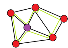
A minimum spanning tree (MST) or minimum weight spanning tree is a subset of the edges of a connected, edge-weighted undirected graph that connects all the vertices together, without any cycles and with the minimum possible total edge weight. That is, it is a spanning tree whose sum of edge weights is as small as possible. More generally, any edge-weighted undirected graph has a minimum spanning forest, which is a union of the minimum spanning trees for its connected components.

The Hamiltonian path problem is a topic discussed in the fields of complexity theory and graph theory. It decides if a directed or undirected graph, G, contains a Hamiltonian path, a path that visits every vertex in the graph exactly once. The problem may specify the start and end of the path, in which case the starting vertex s and ending vertex t must be identified.

Link-state routing protocols are one of the two main classes of routing protocols used in packet switching networks for computer communications, the others being distance-vector routing protocols. Examples of link-state routing protocols include Open Shortest Path First (OSPF) and Intermediate System to Intermediate System (IS-IS).

<span class="mw-page-title-main">Spanning tree</span> Tree which includes all vertices of a graph

In the mathematical field of graph theory, a spanning treeT of an undirected graph G is a subgraph that is a tree which includes all of the vertices of G. In general, a graph may have several spanning trees, but a graph that is not connected will not contain a spanning tree. If all of the edges of G are also edges of a spanning tree T of G, then G is a tree and is identical to T.

<span class="mw-page-title-main">Wireless mesh network</span> Radio nodes organized in a mesh topology

A wireless mesh network (WMN) is a communications network made up of radio nodes organized in a mesh topology. It can also be a form of wireless ad hoc network.

<span class="mw-page-title-main">Mesh networking</span> Network with multiple links between nodes

A mesh network is a local area network topology in which the infrastructure nodes connect directly, dynamically and non-hierarchically to as many other nodes as possible and cooperate with one another to efficiently route data to and from clients.

<span class="mw-page-title-main">Optimized Link State Routing Protocol</span> IP routing protocol optimized for mobile ad hoc networks

The Optimized Link State Routing Protocol (OLSR) is an IP routing protocol optimized for mobile ad hoc networks, which can also be used on other wireless ad hoc networks. OLSR is a proactive link-state routing protocol, which uses hello and topology control (TC) messages to discover and then disseminate link state information throughout the mobile ad hoc network. Individual nodes use this topology information to compute next hop destinations for all nodes in the network using shortest hop forwarding paths.

<span class="mw-page-title-main">Pathfinding</span> Plotting by a computer application

Pathfinding or pathing is the plotting, by a computer application, of the shortest route between two points. It is a more practical variant on solving mazes. This field of research is based heavily on Dijkstra's algorithm for finding the shortest path on a weighted graph.

The Hazy-Sighted Link State Routing Protocol (HSLS) is a wireless mesh network routing protocol being developed by the CUWiN Foundation. This is an algorithm allowing computers communicating via digital radio in a mesh network to forward messages to computers that are out of reach of direct radio contact. Its network overhead is theoretically optimal, utilizing both proactive and reactive link-state routing to limit network updates in space and time. Its inventors believe it is a more efficient protocol to route wired networks as well. HSLS was invented by researchers at BBN Technologies.

The MENTOR routing algorithm is an algorithm for use in routing of mesh networks, specifically pertaining to their initial topology. It was developed in 1991 by Aaron Kershenbaum, Parviz Kermani, and George A. Grove and was published by the IEEE.

In telecommunications, subnetwork connection protection (SNCP), is a type of protection mechanism associated with synchronous optical networks such as synchronous digital hierarchy (SDH).

<span class="mw-page-title-main">OCARI</span>

OCARI is a low-rate wireless personal area networks (LR-WPAN) communication protocol that derives from the IEEE 802.15.4 standard. It was developed by the following consortium during the OCARI project that is funded by the French National Research Agency (ANR):

<span class="mw-page-title-main">Optical mesh network</span> Optical network using a mesh topology

An optical mesh network is a type of optical telecommunications network employing wired fiber-optic communication or wireless free-space optical communication in a mesh network architecture.

Shared risk resource group is a concept in optical mesh network routing that different networks may suffer from a common failure if they share a common risk or a common SRG. SRG is not limited to Optical mesh networks: SRGs are also used in MPLS, IP networks, and synchronous optical networks.

<span class="mw-page-title-main">Multicast lightpaths</span> Type of computer communication

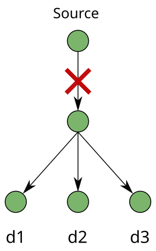
A multicast session requires a "point-to-multipoint" connection from a source node to multiple destination nodes. The source node is known as the root. The destination nodes are known as leaves. In the modern era, it is important to protect multicast connections in an optical mesh network. Recently, multicast applications have gained popularity as they are important to protecting critical sessions against failures such as fiber cuts, hardware faults, and natural disasters.

Link protection is designed to safeguard networks from failure. Failures in high-speed networks have always been a concern of utmost importance. A single fiber cut can lead to heavy losses of traffic and protection-switching techniques have been used as the key source to ensure survivability in networks. Survivability can be addressed in many layers in a network and protection can be performed at the physical layer, Layer 2 and Layer 3 (IP).

Path protection in telecommunications is an end-to-end protection scheme used in connection oriented circuits in different network architectures to protect against inevitable failures on service providers’ network that might affect the services offered to end customers. Any failure occurred at any point along the path of a circuit will cause the end nodes to move/pick the traffic to/from a new route. Finding paths with protection, especially in elastic optical networks, was considered a difficult problem, but an efficient and optimal algorithm was proposed.

Segment protection is a type of backup technique that can be used in most networks. It can be implemented as a dedicated backup or as a shared backup protection. Overlapping segments and non-overlapping segments are allowed; each providing different advantages.

Fast automatic restoration (FASTAR) is an automated fast response system developed and deployed by American Telephone & Telegraph (AT&T) in 1992 for the centralized restoration of its digital transport network. FASTAR automatically reroutes circuits over a spare protection capacity when a fiber-optic cable failure is detected, hence increasing service availability and reducing the impact of the outages in the network. Similar in operation is real-time restoration (RTR), developed and deployed by MCI and used in the MCI network to minimize the effects of a fiber cut.

References

  1. 1 2 3 4 5 6 7 8 9 10 11 12 Asthana, R.; Singh, Y.N.; Grover, W.D.; , "p-Cycles: An overview," IEEE Communications Surveys and Tutorials , vol.12, no.1, pp.97-111, First Quarter 2010
  2. Grover, Wayne. "Announcing". John Wiley & Sons. Retrieved 3 December 2012.
  3. 1 2 Claus G. Gruber and Dominic A. Schupke.; , "Capacity-efficient Planning of Resilient Networks with p-Cycles,". 2002.
  4. Kodian, A.; Sack, A.; Grover, W.D.; , "p-cycle network design with hop limits and circumference limits," Broadband Networks, 2004. BroadNets 2004. Proceedings. First International Conference on , vol., no., pp. 244- 253, 25-29 Oct. 2004
  5. Onguetou, D.P.; Grover, W.D.; , "p-cycle network design: From fewest in number to smallest in size," Design and Reliable Communication Networks, 2007. DRCN 2007. 6th International Workshop on , vol., no., pp.1-8, 7-10 Oct. 2007
  6. 1 2 Zhenrong Zhang; Wen-De Zhong; Mukherjee, B.; , "A heuristic method for design of survivable WDM networks with p-cycles," IEEE Communications Letters , vol.8, no.7, pp. 467- 469, July 2004
  7. H. Hwang, S. Y. Ahn, Y. H. Yoo, and S. K. Chong, “Multiple shared backup cycles for survivable optical networks,” in Proc. ICCCN’01, Scottsdale, AZ, Oct. 2001, pp. 284–289.
  8. 1 2 3 Doucette, J.; He, D.; Grover, W.D.; Yang, O.; , "Algorithmic approaches for efficient enumeration of candidate p-cycles and capacitated p-cycle network design," Design of Reliable Communication Networks, 2003. (DRCN 2003). Proceedings. Fourth International Workshop on , vol., no., pp. 212- 220, 19-22 Oct. 2003
  9. 1 2 3 Grover, W.D.; Stamatelakis, D.; , "Cycle-oriented distributed preconfiguration: ring-like speed with mesh-like capacity for self-planning network restoration," Communications, 1998. ICC 98. Conference Record. 1998 IEEE International Conference on , vol.1, no., pp.537-543 vol.1, 7-11 Jun 1998
  10. W.D. Grover, Mesh-based Survivable Networks: Options for Optical, MPLS, SONET and ATM Networking, Prentice-Hall, Aug. 2003.