PLPAK

Last updated

The PLPAK developers, BE4E, describe it as "The PLPAK is special purpose software package for structural analysis of building slabs and foundations based on the Boundary Element Method". [1] The PLPAK uses the shear-deformable plate bending theory according to Reissner.

Contents

Technical publications

This package is developed by Prof. Youssef F. Rashed with his research group. The following are some relevant publications:

  1. Rashed, Y. F., Boundary Element Formulations for Thick Plates, Topics in engineering, Vol. 35. WIT press, Southampton and Boston, (2000).
  2. Rashed, Y. F., C.A. Brebbia, Eds., Transformation of domain effects to the boundary, WIT press, Southampton and Boston, (2003).
  3. Rashed, Y. F., Aliabadi, M.H., Brebbia, C.A., Transformation of domain integrals in BEM for thick foundation plates. ASCE J. Engineering Mechanics, 125(9), 1062-1070 (1999).
  4. Rashed, Y. F., Aliabadi, M.H., Boundary element analysis of building foundation plates. Engineering Analysis with Boundary Element, 24, 201–206, (2000).
  5. Rashed, Y. F. A boundary integral transformation for bending analysis of thick plates resting on bi-parameter foundation. Advances in Structural Engineering, 5(1), 13-22, (2002).
  6. Rashed, Y. F., A coupled BEM-flexibility force method for bending analysis of internally supported plates. Int. J. Numerical Methods in Engineering, 54, 1431–1457, (2002).
  7. Rashed, Y. F., BEM for dynamic analysis using compact supported radial basis functions, Computers & Structures, 80, 1351–1367, (2002).
  8. Rashed, Y. F., Boundary element modelling of flat plate floors under vertical loading, Int. J. Numerical Methods in Engineering, 62, 1606–1635, (2005).
  9. Rashed, Y. F., A boundary/domain element method for analysis of building raft foundations, Engineering Analysis with Boundary Elements, 29, 859-877, (2005).
  10. Rashed, Y. F., A relative quantity integral equation formulation for evaluation of boundary stress resultants in shear deformable plate bending problems, Eng. Analysis with Boundary Elements 32, 152–161, (2008).

Applications

The PLPAK can be used to do structural analysis for:

Modelling capabilities

The analysis using the PLPAK allows the modeler to make use of the advantages of the boundary element modeling. The PLPAK user has the ability to:

  1. Accurate modeling of problem geometry including geometry of different structural elements (beams, prestressing cables etc....) and fine details.
  2. Ability to model the area connection between the plate and other structural elements.
  3. The ability to get highly accurate local results in different forms that would be required in design e.g. strips and local contours.
  4. Results can be displayed in different forms e.g. bending moment, twisting moment, highly accurate shear results and displacements. Moreover, the PLPAK provides the user with the design moment based on Wood and Armur equation that includes the effect of torsion moment.
  5. Easy input of structural model using DXF import.
  6. Ability to do multiple update of the post-tensioning cables to the model during the design process.
  7. Small disk space, even huge models are mailable.
  8. The PLPAK can provide the user with soil reaction map in foundation problems.

Software components

The PLPAK software is an integrated development environment helps the user to generate his model using the PLGen module. It allows the user to view or/and edit the used boundary element model via the PLView module. Hence he can solve it using the PLCoreMan module. The PLPost module serves as a post-processing module for the obtained results. The package could be linked to other packages such as the PTPAK which provide the capability of adding post-tensioned cables to the model. The proposed PLPAK package consists mainly of five main parts (separate modules) as follows:

  1. The BE model generator (the PLGen module).
  2. The BE model viewer (the PLView module).
  3. The core solver module (the PLCoreMan module).
  4. The post-processor (the PLPost module).
  5. The post-tension module (PTPAK).

The PLGen module

The PLGen module stands for the virtual model generator or the pre-processor of the PLPAK. It mainly changes any structural drawing to what is called the "virtual model". Modeller can import structural drawings from DXF CAD files or can draw then directly using the CAD capabilities of the PLGen. The virtual model looks very similar to the original structural drawing. The PLGen mainly define the structure using series of objects. These objects are classified into one of three categories: the geometrical objects (single slab and openings), the loading objects (column load, wall load, load patch, load assembly) and the supporting objects (column, wall, wall assembly, soil support, beam). Using such objects the modeler can define all elements in the building slab. It has to be noted that the virtual model represents the actual slab shape (not like the centre-line model of the finite element method). Columns and walls are represented by the actual cross section shape. The PLGen can also input the numerical models of each object such as the number of boundary elements for each segments, the discretization of the beam-slab contact areas, etc. Load cases only (i.e. no load combinations) are defined in the PLGen module. Material properties are also defined herein. The below Figure demonstrates the graphical user interface of the PLGen module.

The following table states the types of objects available in the PLGEn module.

Structural ObjectTypical modeling usages
SlabModeling building slabs and foundations
OpeningAdd openings to the slab object
Column/PileModeling supports of mean dimensions like most of structural columns supporting Building slabs or Piles supporting foundations
BeamModeling of beams supporting the slabs
Wall SupportModeling supports elongated in one direction like a buildings shear walls
Support AssemblyModeling supports of complex geometry like buildings cores or broken shear walls
Load PatchesAdd a distributed load over a quadrilateral part of the slab object
Column LoadAdd vertical force and two moments over a quadrilateral part of the slab object
Wall LoadModeling Loads elongated in one direction like a buildings shear walls loads over a raft foundation and loads over slabs due to brick walls
Load AssemblyModeling Loads of complex geometry like buildings cores loads over a raft foundation
Soil SupportModeling the soil supporting the building foundation

The capabilities of this module can be summarized as follows:

  1. Construct a virtual structural model for the problem using object-based modeling. This is proposed to be done through an interactive graphical interface that can construct and edit the virtual model.
  2. Generate a BE model from the virtual model.
  3. Control the generated BE model through the graphical interface using parameters settings.
  4. Import CAD drawings to facilitate the construction of the virtual model.
  5. Store the virtual model in a binary form so that it can be recalled later.
  6. Undo and redo changes made to the virtual model.
  7. Construct a 3D view of the virtual structural model.
  8. Handling different load cases and generating a BE model for each one.
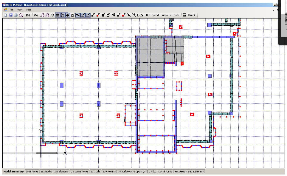
The PLView module

The PLView module is a MDI (multiple document interface) graphical environment that allows the modeller to view or/and to edit the boundary element numerical model of the considered problem. Boundary element discretization and internal loading or supporting patches are viewed. The PLView could be launched directly from the PLGen module. Practical engineers or beginners can skip this module. It has to be noted that the expert modellers can write their own input text file for the considered numerical model and input it directly to the PLView model without passing through the PLGen module. The below Figure demonstrates the graphical user interface of the PLView module.

This is the BE model viewer that is developed to visualize the generated boundary element models generated by the PLGen module or from user text input. This module has also some model editing capabilities that are considered a secondary benefit. Only advanced users who have thorough understanding of boundary element modeling can make use of this feature. The core component of this module is proposed to be a dataset that contains data tables of all the entities forming the model. This dataset can be thought of as a database that resides in the computer memory rather than on the computer hard disk. This technique is usually faster for data centric applications especially when the size of data is not large, as the case when using BEM. The dataset is populated using the data that already exist in the input text file (*.in) and then the populated dataset is used to visualize the model. The model data typically consist of material parameters, linear equation solver parameters, nodes coordinates, points coordinates, elements connectivity data, columns definition, cells definition and internal points coordinates.

PLview.PNG

The capabilities of the BE model viewer can be summarized in the following:

  1. Display all the model data graphically.
  2. Display all the model data in tabular form.
  3. Edit the model data in the tables.
  4. Store the model again in text format after editing.

The PLCoreMan module

The PLCoreMan module serves as a link between all of the PLPAK modules. It allows solution for multiple load cases. It also allows adding any additional loading (such as pre-stressing loading) or sophisticated supporting elements (such as any substructure). It also acts as solution tracer.

PLCore.PNG

This is the part of the PLPAK that is responsible for solving the boundary element model (saved by the PLGen) using Reissner plate bending equations. The main part of the module is the PL.exe which is the core solver. This module allows the user to add post tensioning cables and updates the input files according to the cables added. The below Figure demonstrates the generic operation diagram for the PL.exe core solver.
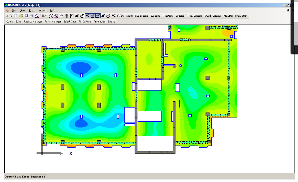
The PLPost module

The PLPost module allows the user to display the results in forms of strips, contours, and colour patches. It has to be noted that all results obtained in the PLPost environment are computed using analytical integral equations. In other words, no approximation is involved. Load combinations are defined herein. Results of any form could be exported easily to text files or to spreadsheets programs. The below Figure demonstrates the graphical user interface of the PLPost module.

PLPost.PNG

The proposed capabilities of the post processor can be summarized in the following:

  1. Represent the results at a point.
  2. Represent the results along a line.
  3. Represent the results over an area using contour plots.
  4. Export the results in formatted text files.
  5. Store the results in a binary form, so that it can be recalled without repeating the analysis.
  6. Perform the load combinations of different load cases.
  7. Display the columns reactions or soil contact pressures under the raft graphically.

The PTPAK module

The PTPAK is the software component responsible for the creation of cable profiles and updating them to the structural model.

Related Research Articles

User interface Means by which a user interacts with and controls a machine

In the industrial design field of human–computer interaction, a user interface (UI) is the space where interactions between humans and machines occur. The goal of this interaction is to allow effective operation and control of the machine from the human end, while the machine simultaneously feeds back information that aids the operators' decision-making process. Examples of this broad concept of user interfaces include the interactive aspects of computer operating systems, hand tools, heavy machinery operator controls, and process controls. The design considerations applicable when creating user interfaces are related to, or involve such disciplines as, ergonomics and psychology.

Structural engineering Sub-discipline of civil engineering dealing with the creation of man made structures

Structural engineering is a sub-discipline of civil engineering in which structural engineers are trained to design the 'bones and muscles' that create the form and shape of man-made structures. Structural engineers also must understand and calculate the stability, strength, rigidity and earthquake-susceptibility of built structures for buildings and nonbuilding structures. The structural designs are integrated with those of other designers such as architects and building services engineer and often supervise the construction of projects by contractors on site. They can also be involved in the design of machinery, medical equipment, and vehicles where structural integrity affects functioning and safety. See glossary of structural engineering.

Software design is the process by which an agent creates a specification of a software artifact intended to accomplish goals, using a set of primitive components and subject to constraints. Software design may refer to either "all the activity involved in conceptualizing, framing, implementing, commissioning, and ultimately modifying complex systems" or "the activity following requirements specification and before programming, as ... [in] a stylized software engineering process."

Structural analysis is a branch of Solid Mechanics which uses simplified models for solids like bars, beams and shells for engineering decision making. It's main objective is to determine the effect of loads on the physical structures and their components. In contrast to theory of elasticity, the models used in structure analysis are often differential equations in one spatial variable. Structures subject to this type of analysis include all that must withstand loads, such as buildings, bridges, aircraft and ships. Structural analysis uses ideas from applied mechanics, materials science and applied mathematics to compute a structure's deformations, internal forces, stresses, support reactions, velocity, accelerations, and stability. The results of the analysis are used to verify a structure's fitness for use, often precluding physical tests. Structural analysis is thus a key part of the engineering design of structures.

Graphical widget Element of interaction in a graphical user interface

A graphical widget in a graphical user interface is an element of interaction, such as a button or a scroll bar. Controls are software components that a computer user interacts with through direct manipulation to read or edit information about an application. User interface libraries such as Windows Presentation Foundation, Qt, GTK, and Cocoa, contain a collection of controls and the logic to render these.

A read–eval–print loop (REPL), also termed an interactive toplevel or language shell, is a simple interactive computer programming environment that takes single user inputs, executes them, and returns the result to the user; a program written in a REPL environment is executed piecewise. The term usually refers to programming interfaces similar to the classic Lisp machine interactive environment. Common examples include command-line shells and similar environments for programming languages, and the technique is very characteristic of scripting languages.

The finite element method (FEM) is a powerful technique originally developed for numerical solution of complex problems in structural mechanics, and it remains the method of choice for complex systems. In the FEM, the structural system is modeled by a set of appropriate finite elements interconnected at discrete points called nodes. Elements may have physical properties such as thickness, coefficient of thermal expansion, density, Young's modulus, shear modulus and Poisson's ratio.

Crash simulation Virtual recreation of a destructive car crash

A crash simulation is a virtual recreation of a destructive crash test of a car or a highway guard rail system using a computer simulation in order to examine the level of safety of the car and its occupants. Crash simulations are used by automakers during computer-aided engineering (CAE) analysis for crashworthiness in the computer-aided design (CAD) process of modelling new cars. During a crash simulation, the kinetic energy, or energy of motion, that a vehicle has before the impact is transformed into deformation energy, mostly by plastic deformation (plasticity) of the car body material, at the end of the impact.

VE-Suite is an open source based virtual engineering software toolkit that simplifies information management so users can simultaneously interact with engineering analyses and graphical models to create a virtual decision-making environment. It is available under the GNU Lesser General Public License (LGPL) and is composed of four main software engines:

In computer science, marshalling or marshaling is the process of transforming the memory representation of an object into a data format suitable for storage or transmission. It is typically used when data must be moved between different parts of a computer program or from one program to another.

Specialized wind energy software applications aid in the development and operation of wind farms.

Z88 is a software package for the finite element method (FEM) and topology optimization. A team led by Frank Rieg at the University of Bayreuth started development in 1985 and now the software is used by several universities, as well as small and medium-sized enterprises. Z88 is capable of calculating two and three dimensional element types with a linear approach. The software package contains several solvers and two post-processors and is available for Microsoft Windows, Mac OS X and Unix/Linux computers in 32-bit and 64-bit versions. Benchmark tests conducted in 2007 showed a performance on par with commercial software.

Structural engineering theory

Structural engineering depends upon a detailed knowledge of loads, physics and materials to understand and predict how structures support and resist self-weight and imposed loads. To apply the knowledge successfully structural engineers will need a detailed knowledge of mathematics and of relevant empirical and theoretical design codes. They will also need to know about the corrosion resistance of the materials and structures, especially when those structures are exposed to the external environment.

Endevor is a source code management and release management tool for mainframe computers running z/OS . It is part of a family of administration tools by CA Technologies, which is used to maintain software applications and track their versions as well as automate lifecycle activities like builds and deployments.

STAAD or (STAAD.Pro) is a structural analysis and design software application originally developed by Research Engineers International in 1997. In late 2005, Research Engineers International was bought by Bentley Systems. STAAD stands for STructural Analysis And Design.

ADINA is a commercial engineering simulation software program that is developed and distributed worldwide by ADINA R & D, Inc. The company was founded in 1986 by Dr. Klaus-Jürgen Bathe, and is headquartered in Watertown, Massachusetts, United States. On April 7, 2022, Bentley Systems acquired ADINA R&D, Inc.

QBlade is an open-source, cross-platform simulation software for wind turbine blade design and aerodynamic simulation. It comes with a user-friendly graphical user interface (GUI) based on Qt.

VisualFEA

VisualFEA is a finite element analysis software program for Microsoft Windows and Mac OS X. It is developed and distributed by Intuition Software, Inc. of South Korea, and used chiefly for structural and geotechnical analysis. Its strongest point is its intuitive, user-friendly design based on graphical pre- and postprocessing capabilities. It has educational features for teaching and learning structural mechanics, and finite element analysis through graphical simulation. It is widely used in college-level courses related to structural mechanics and finite element methods.

ACTRAN is a finite element-based computer aided engineering software modeling the acoustic behavior of mechanical systems and parts. Actran is being developed by Free Field Technologies, a Belgian software company founded in 1998 by Jean-Pierre Coyette and Jean-Louis Migeot. Free Field Technologies is a wholly owned subsidiary of the MSC Software Corporation since 2011. Free Field Technologies and MSC Software are part of Hexagon AB since 2017.

FEATool Multiphysics

FEATool Multiphysics is a physics, finite element analysis (FEA), and PDE simulation toolbox. FEATool Multiphysics features the ability to model fully coupled heat transfer, fluid dynamics, chemical engineering, structural mechanics, fluid-structure interaction (FSI), electromagnetics, as well as user-defined and custom PDE problems in 1D, 2D (axisymmetry), or 3D, all within a graphical user interface (GUI) or optionally as script files. FEATool has been employed and used in academic research, teaching, and industrial engineering simulation contexts.

References

  1. "Home". be4e.com.

plpak daddy