In the power systems analysis field of electrical engineering, a per-unit system is the expression of system quantities as fractions of a defined base unit quantity. Calculations are simplified because quantities expressed as per-unit do not change when they are referred from one side of a transformer to the other. This can be a pronounced advantage in power system analysis where large numbers of transformers may be encountered. Moreover, similar types of apparatus will have the impedances lying within a narrow numerical range when expressed as a per-unit fraction of the equipment rating, even if the unit size varies widely. Conversion of per-unit quantities to volts, ohms, or amperes requires a knowledge of the base that the per-unit quantities were referenced to. The per-unit system is used in power flow, short circuit evaluation, motor starting studies etc.
The main idea of a per unit system is to absorb large differences in absolute values into base relationships. Thus, representations of elements in the system with per unit values become more uniform.
A per-unit system provides units for power, voltage, current, impedance, and admittance. With the exception of impedance and admittance, any two units are independent and can be selected as base values; power and voltage are typically chosen. All quantities are specified as multiples of selected base values. For example, the base power might be the rated power of a transformer, or perhaps an arbitrarily selected power which makes power quantities in the system more convenient. The base voltage might be the nominal voltage of a bus. Different types of quantities are labeled with the same symbol (pu); it should be clear whether the quantity is a voltage, current, or other unit of measurement.
Purpose
There are several reasons for using a per-unit system:
Similar apparatus (generators, transformers, lines) will have similar per-unit impedances and losses expressed on their own rating, regardless of their absolute size. Because of this, per-unit data can be checked rapidly for gross errors. A per unit value out of normal range is worth looking into for potential errors.
Manufacturers usually specify the impedance of apparatus in per unit values.
Use of the constant is reduced in three-phase calculations.
Per-unit quantities are the same on either side of a transformer, independent of voltage level
By normalizing quantities to a common base, both hand and automatic calculations are simplified.
It improves numerical stability of automatic calculation methods.
Per unit data representation yields important information about relative magnitudes.
The per-unit system was developed to make manual analysis of power systems easier. Although power-system analysis is now done by computer, results are often expressed as per-unit values on a convenient system-wide base.
Base quantities
Generally base values of power and voltage are chosen. The base power may be the rating of a single piece of apparatus such as a motor or generator. If a system is being studied, the base power is usually chosen as a convenient round number such as 10MVA or 100MVA. The base voltage is chosen as the nominal rated voltage of the system. All other base quantities are derived from these two base quantities. Once the base power and the base voltage are chosen, the base current and the base impedance are determined by the natural laws of electrical circuits. The base value should only be a magnitude, while the per-unit value is a phasor. The phase angles of complex power, voltage, current, impedance, etc., are not affected by the conversion to per unit values.
The purpose of using a per-unit system is to simplify conversion between different transformers. Hence, it is appropriate to illustrate the steps for finding per-unit values for voltage and impedance. First, let the base power (Sbase) of each end of a transformer become the same. Once every S is set on the same base, the base voltage and base impedance for every transformer can easily be obtained. Then, the real numbers of impedances and voltages can be substituted into the per-unit calculation definition to get the answers for the per-unit system. If the per-unit values are known, the real values can be obtained by multiplying by the base values.
By convention, the following two rules are adopted for base quantities:
The base power value is the same for the entire power system of concern.
The ratio of the voltage bases on either side of a transformer is selected to be the same as the ratio of the transformer voltage ratings.
With these two rules, a per-unit impedance remains unchanged when referred from one side of a transformer to the other. This allows the ideal transformer to be eliminated from a transformer model.
Relationship between units
The relationship between units in a per-unit system depends on whether the system is single-phase or three-phase.
Single-phase
Assuming that the independent base values are power and voltage, we have:
Alternatively, the base value for power may be given in terms of reactive or apparent power, in which case we have, respectively,
or
The rest of the units can be derived from power and voltage using the equations , , and (Ohm's law), being represented by . We have:
Three-phase
Power and voltage are specified in the same way as single-phase systems. However, due to differences in what these terms usually represent in three-phase systems, the relationships for the derived units are different. Specifically, power is given as total (not per-phase) power, and voltage is line-to-line voltage. In three-phase systems the equations and also hold. The apparent power now equals
Example of per-unit
As an example of how per-unit is used, consider a three-phase power transmission system that deals with powers of the order of 500 MW and uses a nominal voltage of 138 kV for transmission. We arbitrarily select , and use the nominal voltage 138 kV as the base voltage . We then have:
If, for example, the actual voltage at one of the buses is measured to be 136 kV, we have:
Per-unit system formulas
The following tabulation of per-unit system formulas is adapted from Beeman's Industrial Power Systems Handbook.
Equation
Base number selection
Arbitrarily selecting from ohm's law the two base numbers: base voltage and base current
1
2
3
4
5
Alternatively, choosing base volts and base kva values, we have,
in single-phase systems:
6
7
8
and in three-phase systems:
9
10
11
Working out for convenience per-unit ohms directly, we have
for single-phase and three-phase systems:
12
Short-Circuit Calculation Formulas
Ohms conversions:
13
14
15
Changing ohms from one kva base to another:
16
17
Changing incoming system reactance:
a. If system reactance is given in percent, use Eq. 16 to change from one kva base to another.
b. If system reactance is given in short-circuit symmetrical rms kva or current, convert to per-unit as follows:
18
19
Calculating approximate motor kva base:
a. For induction motors and 0.8 power factor synchronous motors
20
b. For unity power factor synchronous motors
21
Converting ohms from one voltage to another:
22
Short-circuit kva and current calculations
Symmetrical short circuit kva:
23
24
25
26
Symmetrical short circuit current:
27
28
29
Asymmetrical short-circuit current and kva:
30
31
In transformers
It can be shown that voltages, currents, and impedances in a per-unit system will have the same values whether they are referred to primary or secondary of a transformer.[1]:85
For instance, for voltage, we can prove that the per unit voltages of two sides of the transformer, side 1 and side 2, are the same. Here, the per-unit voltages of the two sides are E1pu and E2pu respectively.
(source: Alexandra von Meier Power System Lectures, UC Berkeley)
E1 and E2 are the voltages of sides 1 and 2 in volts. N1 is the number of turns the coil on side 1 has. N2 is the number of turns the coil on side 2 has. Vbase1 and Vbase2 are the base voltages on sides 1 and 2.
For current, we can prove that the per-unit currents of the two sides are the same below.
(source: Alexandra von Meier Power System Lectures, UC Berkeley)
where I1,pu and I2,pu are the per-unit currents of sides 1 and 2 respectively. In this, the base currents Ibase1 and Ibase2 are related in the opposite way that Vbase1 and Vbase2 are related, in that
The reason for this relation is for power conservation
Sbase1 = Sbase2
The full load copper loss of a transformer in per-unit form is equal to the per-unit value of its resistance:
Therefore, it may be more useful to express the resistance in per-unit form as it also represents the full-load copper loss.[1]:86
As stated above, there are two degrees of freedom within the per unit system that allow the engineer to specify any per unit system. The degrees of freedom are the choice of the base voltage (Vbase) and the base power (Sbase). By convention, a single base power (Sbase) is chosen for both sides of the transformer and its value is equal to the rated power of the transformer. By convention, there are actually two different base voltages that are chosen, Vbase1 and Vbase2 which are equal to the rated voltages for either side of the transformer. By choosing the base quantities in this manner, the transformer can be effectively removed from the circuit as described above. For example:
Take a transformer that is rated at 10kVA and 240/100V. The secondary side has an impedance equal to 1∠0°Ω. The base impedance on the secondary side is equal to:
This means that the per unit impedance on the secondary side is 1∠0°Ω / 1Ω = 1∠0°pu When this impedance is referred to the other side, the impedance becomes:
The base impedance for the primary side is calculated the same way as the secondary:
This means that the per unit impedance is 5.76∠0°Ω / 5.76Ω = 1∠0°pu, which is the same as when calculated from the other side of the transformer, as would be expected.
Another useful tool for analyzing transformers is to have the base change formula that allows the engineer to go from a base impedance with one set of a base voltage and base power to another base impedance for a different set of a base voltage and base power. This becomes especially useful in real life applications where a transformer with a secondary side voltage of 1.2kV might be connected to the primary side of another transformer whose rated voltage is 1kV. The formula is as shown below.
Related Research Articles
Conversion of units is the conversion of the unit of measurement in which a quantity is expressed, typically through a multiplicative conversion factor that changes the unit without changing the quantity. This is also often loosely taken to include replacement of a quantity with a corresponding quantity that describes the same physical property.
The Fresnel equations describe the reflection and transmission of light when incident on an interface between different optical media. They were deduced by French engineer and physicist Augustin-Jean Fresnel who was the first to understand that light is a transverse wave, when no one realized that the waves were electric and magnetic fields. For the first time, polarization could be understood quantitatively, as Fresnel's equations correctly predicted the differing behaviour of waves of the s and p polarizations incident upon a material interface.
Power is the amount of energy transferred or converted per unit time. In the International System of Units, the unit of power is the watt, equal to one joule per second. Power is a scalar quantity.
The characteristic impedance or surge impedance (usually written Z0) of a uniform transmission line is the ratio of the amplitudes of voltage and current of a wave travelling in one direction along the line in the absence of reflections in the other direction. Equivalently, it can be defined as the input impedance of a transmission line when its length is infinite. Characteristic impedance is determined by the geometry and materials of the transmission line and, for a uniform line, is not dependent on its length. The SI unit of characteristic impedance is the ohm.
In electrical engineering, a transmission line is a specialized cable or other structure designed to conduct electromagnetic waves in a contained manner. The term applies when the conductors are long enough that the wave nature of the transmission must be taken into account. This applies especially to radio-frequency engineering because the short wavelengths mean that wave phenomena arise over very short distances. However, the theory of transmission lines was historically developed to explain phenomena on very long telegraph lines, especially submarine telegraph cables.
In electrical engineering, impedance is the opposition to alternating current presented by the combined effect of resistance and reactance in a circuit.
A rectifier is an electrical device that converts alternating current (AC), which periodically reverses direction, to direct current (DC), which flows in only one direction. The reverse operation is performed by an inverter.
In electrical engineering, the maximum power transfer theorem states that, to obtain maximum external power from a power source with internal resistance, the resistance of the load must equal the resistance of the source as viewed from its output terminals. Moritz von Jacobi published the maximum power (transfer) theorem around 1840; it is also referred to as "Jacobi's law".
Inductance is the tendency of an electrical conductor to oppose a change in the electric current flowing through it. The electric current produces a magnetic field around the conductor. The magnetic field strength depends on the magnitude of the electric current, and follows any changes in the magnitude of the current. From Faraday's law of induction, any change in magnetic field through a circuit induces an electromotive force (EMF) (voltage) in the conductors, a process known as electromagnetic induction. This induced voltage created by the changing current has the effect of opposing the change in current. This is stated by Lenz's law, and the voltage is called back EMF.
In radio and telecommunications a dipole antenna or doublet is one of the two simplest and most widely-used types of antenna; the other is the monopole. The dipole is any one of a class of antennas producing a radiation pattern approximating that of an elementary electric dipole with a radiating structure supporting a line current so energized that the current has only one node at each far end. A dipole antenna commonly consists of two identical conductive elements such as metal wires or rods. The driving current from the transmitter is applied, or for receiving antennas the output signal to the receiver is taken, between the two halves of the antenna. Each side of the feedline to the transmitter or receiver is connected to one of the conductors. This contrasts with a monopole antenna, which consists of a single rod or conductor with one side of the feedline connected to it, and the other side connected to some type of ground. A common example of a dipole is the "rabbit ears" television antenna found on broadcast television sets. All dipoles are electrically equivalent to two monopoles mounted end-to-end and fed with opposite phases, with the ground plane between them made "virtual" by the opposing monopole.
An LC circuit, also called a resonant circuit, tank circuit, or tuned circuit, is an electric circuit consisting of an inductor, represented by the letter L, and a capacitor, represented by the letter C, connected together. The circuit can act as an electrical resonator, an electrical analogue of a tuning fork, storing energy oscillating at the circuit's resonant frequency.
In electrical engineering and electronics, a network is a collection of interconnected components. Network analysis is the process of finding the voltages across, and the currents through, all network components. There are many techniques for calculating these values; however, for the most part, the techniques assume linear components. Except where stated, the methods described in this article are applicable only to linear network analysis.
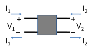
In electronics, a two-port network is an electrical network or device with two pairs of terminals to connect to external circuits. Two terminals constitute a port if the currents applied to them satisfy the essential requirement known as the port condition: the current entering one terminal must equal the current emerging from the other terminal on the same port. The ports constitute interfaces where the network connects to other networks, the points where signals are applied or outputs are taken. In a two-port network, often port 1 is considered the input port and port 2 is considered the output port.
In an electric circuit, instantaneous power is the time rate of flow of energy past a given point of the circuit. In alternating current circuits, energy storage elements such as inductors and capacitors may result in periodic reversals of the direction of energy flow. Its SI unit is the watt.
Scattering parameters or S-parameters describe the electrical behavior of linear electrical networks when undergoing various steady state stimuli by electrical signals.
Ripple in electronics is the residual periodic variation of the DC voltage within a power supply which has been derived from an alternating current (AC) source. This ripple is due to incomplete suppression of the alternating waveform after rectification. Ripple voltage originates as the output of a rectifier or from generation and commutation of DC power.
The gyrator–capacitor model - sometimes also the capacitor-permeance model - is a lumped-element model for magnetic circuits, that can be used in place of the more common resistance–reluctance model. The model makes permeance elements analogous to electrical capacitance rather than electrical resistance. Windings are represented as gyrators, interfacing between the electrical circuit and the magnetic model.
An RLC circuit is an electrical circuit consisting of a resistor (R), an inductor (L), and a capacitor (C), connected in series or in parallel. The name of the circuit is derived from the letters that are used to denote the constituent components of this circuit, where the sequence of the components may vary from RLC.
The impedance analogy is a method of representing a mechanical system by an analogous electrical system. The advantage of doing this is that there is a large body of theory and analysis techniques concerning complex electrical systems, especially in the field of filters. By converting to an electrical representation, these tools in the electrical domain can be directly applied to a mechanical system without modification. A further advantage occurs in electromechanical systems: Converting the mechanical part of such a system into the electrical domain allows the entire system to be analysed as a unified whole.
Performance modelling is the abstraction of a real system into a simplified representation to enable the prediction of performance. The creation of a model can provide insight into how a proposed or actual system will or does work. This can, however, point towards different things to people belonging to different fields of work.
Yuen, Moon H. (Mar–Apr 1974). "Short Circuit ABC--Learn It in an Hour, Use It Anywhere, Memorize No Formula". IEEE Transactions on Industry Applications. IA-10 (2): 261–272. doi:10.1109/TIA.1974.349143.
William D. Jr., Stevenson (1975). Elements of power system analysis (3rded.). New York: McGraw-Hill. ISBN0-07-061285-4.
This page is based on this Wikipedia article Text is available under the CC BY-SA 4.0 license; additional terms may apply. Images, videos and audio are available under their respective licenses.