Related Research Articles

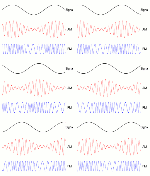
Amplitude modulation (AM) is a modulation technique used in electronic communication, most commonly for transmitting messages with a radio wave. In amplitude modulation, the amplitude of the wave is varied in proportion to that of the message signal, such as an audio signal. This technique contrasts with angle modulation, in which either the frequency of the carrier wave is varied, as in frequency modulation, or its phase, as in phase modulation.

Frequency modulation (FM) is the encoding of information in a carrier wave by varying the instantaneous frequency of the wave. The technology is used in telecommunications, radio broadcasting, signal processing, and computing.
In electronics and telecommunications, modulation is the process of varying one or more properties of a periodic waveform, called the carrier signal, with a separate signal called the modulation signal that typically contains information to be transmitted. For example, the modulation signal might be an audio signal representing sound from a microphone, a video signal representing moving images from a video camera, or a digital signal representing a sequence of binary digits, a bitstream from a computer. The carrier is higher in frequency than the modulation signal. The purpose of modulation is to impress the information on the carrier wave, which is used to carry the information to another location. In radio communication the modulated carrier is transmitted through space as a radio wave to a radio receiver. Another purpose is to transmit multiple channels of information through a single communication medium, using frequency division multiplexing (FDM). For example in cable television which uses FDM, many carrier signals, each modulated with a different television channel, are transported through a single cable to customers. Since each carrier occupies a different frequency, the channels do not interfere with each other. At the destination end, the carrier signal is demodulated to extract the information bearing modulation signal.
Quadrature amplitude modulation (QAM) is the name of a family of digital modulation methods and a related family of analog modulation methods widely used in modern telecommunications to transmit information. It conveys two analog message signals, or two digital bit streams, by changing (modulating) the amplitudes of two carrier waves, using the amplitude-shift keying (ASK) digital modulation scheme or amplitude modulation (AM) analog modulation scheme. The two carrier waves of the same frequency are out of phase with each other by 90°, a condition known as orthogonality or quadrature. The transmitted signal is created by adding the two carrier waves together. At the receiver, the two waves can be coherently separated (demodulated) because of their orthogonality property. Another key property is that the modulations are low-frequency/low-bandwidth waveforms compared to the carrier frequency, which is known as the narrowband assumption.

In radio communications, single-sideband modulation (SSB) or single-sideband suppressed-carrier modulation (SSB-SC) is a type of modulation used to transmit information, such as an audio signal, by radio waves. A refinement of amplitude modulation, it uses transmitter power and bandwidth more efficiently. Amplitude modulation produces an output signal the bandwidth of which is twice the maximum frequency of the original baseband signal. Single-sideband modulation avoids this bandwidth increase, and the power wasted on a carrier, at the cost of increased device complexity and more difficult tuning at the receiver.

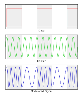
Frequency-shift keying (FSK) is a frequency modulation scheme in which digital information is transmitted through discrete frequency changes of a carrier signal. The technology is used for communication systems such as telemetry, weather balloon radiosondes, caller ID, garage door openers, and low frequency radio transmission in the VLF and ELF bands. The simplest FSK is binary FSK (BFSK). BFSK uses a pair of discrete frequencies to transmit binary information. With this scheme, the 1 is called the mark frequency and the 0 is called the space frequency.
Phase-shift keying (PSK) is a digital modulation process which conveys data by changing (modulating) the phase of a constant frequency reference signal. The modulation is accomplished by varying the sine and cosine inputs at a precise time. It is widely used for wireless LANs, RFID and Bluetooth communication.

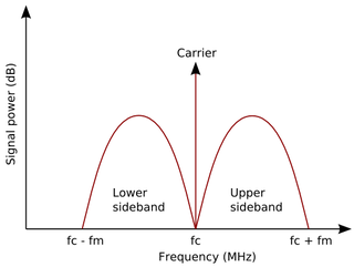
In radio communications, a sideband is a band of frequencies higher than or lower than the carrier frequency, that are the result of the modulation process. The sidebands carry the information transmitted by the radio signal. The sidebands comprise all the spectral components of the modulated signal except the carrier. The signal components above the carrier frequency constitute the upper sideband (USB), and those below the carrier frequency constitute the lower sideband (LSB). All forms of modulation produce sidebands.

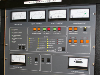
In electronics and telecommunications, a radio transmitter or just transmitter is an electronic device which produces radio waves with an antenna. The transmitter itself generates a radio frequency alternating current, which is applied to the antenna. When excited by this alternating current, the antenna radiates radio waves.
Demodulation is extracting the original information-bearing signal from a carrier wave. A demodulator is an electronic circuit that is used to recover the information content from the modulated carrier wave. There are many types of modulation so there are many types of demodulators. The signal output from a demodulator may represent sound, images or binary data.

In telecommunications, a carrier wave, carrier signal, or just carrier, is a waveform that is modulated (modified) with an information-bearing signal for the purpose of conveying information. This carrier wave usually has a much higher frequency than the input signal does. The purpose of the carrier is usually either to transmit the information through space as an electromagnetic wave, or to allow several carriers at different frequencies to share a common physical transmission medium by frequency division multiplexing. The term originated in radio communication, where the carrier wave creates the waves which carry the information (modulation) through the air from the transmitter to the receiver. The term is also used for an unmodulated emission in the absence of any modulating signal.
Radio-frequency identification (RFID) uses electromagnetic fields to automatically identify and track tags attached to objects. An RFID system consists of a tiny radio transponder, a radio receiver and transmitter. When triggered by an electromagnetic interrogation pulse from a nearby RFID reader device, the tag transmits digital data, usually an identifying inventory number, back to the reader. This number can be used to track inventory goods.
Mode locking is a technique in optics by which a laser can be made to produce pulses of light of extremely short duration, on the order of picoseconds (10−12 s) or femtoseconds (10−15 s). A laser operated in this way is sometimes referred to as a femtosecond laser, for example, in modern refractive surgery. The basis of the technique is to induce a fixed phase relationship between the longitudinal modes of the laser's resonant cavity. Constructive interference between these modes can cause the laser light to be produced as a train of pulses. The laser is then said to be "phase-locked" or "mode-locked".
Continuous phase modulation (CPM) is a method for modulation of data commonly used in wireless modems. In contrast to other coherent digital phase modulation techniques where the carrier phase abruptly resets to zero at the start of every symbol, with CPM the carrier phase is modulated in a continuous manner. For instance, with QPSK the carrier instantaneously jumps from a sine to a cosine whenever one of the two message bits of the current symbol differs from the two message bits of the previous symbol. This discontinuity requires a relatively large percentage of the power to occur outside of the intended band, leading to poor spectral efficiency. Furthermore, CPM is typically implemented as a constant-envelope waveform, i.e., the transmitted carrier power is constant. Therefore, CPM is attractive because the phase continuity yields high spectral efficiency, and the constant envelope yields excellent power efficiency. The primary drawback is the high implementation complexity required for an optimal receiver.
A radio transmitter or just transmitter is an electronic device which produces radio waves with an antenna. Radio waves are electromagnetic waves with frequencies between about 30 Hz and 300 GHz. The transmitter itself generates a radio frequency alternating current, which is applied to the antenna. When excited by this alternating current, the antenna radiates radio waves. Transmitters are necessary parts of all systems that use radio: radio and television broadcasting, cell phones, wireless networks, radar, two way radios like walkie talkies, radio navigation systems like GPS, remote entry systems, among numerous other uses.
Analog transmission is a transmission method of conveying information using a continuous signal which varies in amplitude, phase, or some other property in proportion to that information. It could be the transfer of an analog source signal, using an analog modulation method such as frequency modulation (FM) or amplitude modulation (AM), or no modulation at all.
ISO/IEC 18000-3 is an international standard for passive RFID item level identification and describes the parameters for air interface communications at 13.56 MHz. The target markets for MODE 2 are in tagging systems for manufacturing, logistics, retail, transport and airline baggage. MODE 2 is especially suitable for high speed bulk conveyor fed applications.

The Unified S-band (USB) system is a tracking and communication system developed for the Apollo program by NASA and the Jet Propulsion Laboratory (JPL). It operated in the S band portion of the microwave spectrum, unifying voice communications, television, telemetry, command, tracking and ranging into a single system to save size and weight and simplify operations. The USB ground network was managed by the Goddard Space Flight Center (GSFC). Commercial contractors included Collins Radio, Blaw-Knox, Motorola and Energy Systems.
The IEEE 1902.1-2009 standard is a wireless data communication protocol also known as RuBee, operates within the Low Frequency radio wave range of 30–900 kHz. Although very resistant to interference, metal, water and obstacles, it is very limited in range, usually only suitable for short-range networks. The baud rate is limited to 1,200 kB/s, making it a very low-rate communication network as well. This standard is aimed at the conception of wireless network of sensors and actuators in industrial and military environments. One of the major advantage 1902.1 tags is they are extremely low power and last for years on a simple coin size battery and they can be sealed in a MIL STD 810G package. RuBee tags emit virtually no RF and do not produce any Compromising Emanations, as a result are used in high security facilities. RuBee tags are safe and in use near and on high explosive facilities.
References
- ↑ WO/1999/034526 "Transmitter and Method for Transmitting Data" Archived 2012-08-05 at archive.today .
- ↑ ISO/IEC 18000-3 Section 8 "Table of characteristic differences between the MODES".
- ↑ International Telecommunication Union (ITU).
- ↑ ETSI EN 300 330-1 Archived 2009-07-04 at the Wayback Machine .
- ↑ FCC Title 47 Part 15.
- ↑ ERC/REC 70-03 Archived 2013-08-05 at the Wayback Machine .
- ↑ WO/2008/089507 "Communication Method and Device".
- ↑ RFID Journal Archived 2011-07-19 at the Wayback Machine .