Related Research Articles
In electronics, a logic gate is an idealized or physical device implementing a Boolean function; that is, it performs a logical operation on one or more binary inputs and produces a single binary output. Depending on the context, the term may refer to an ideal logic gate, one that has for instance zero rise time and unlimited fan-out, or it may refer to a non-ideal physical device.
In digital circuit theory, sequential logic is a type of logic circuit whose output depends not only on the present value of its input signals but on the sequence of past inputs, the input history as well. This is in contrast to combinational logic, whose output is a function of only the present input. That is, sequential logic has state (memory) while combinational logic does not.
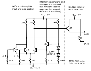
In electronics, emitter-coupled logic (ECL) is a high-speed integrated circuit bipolar transistor logic family. ECL uses an overdriven BJT differential amplifier with single-ended input and limited emitter current to avoid the saturated region of operation and its slow turn-off behavior. As the current is steered between two legs of an emitter-coupled pair, ECL is sometimes called current-steering logic (CSL), current-mode logic (CML) or current-switch emitter-follower (CSEF) logic.
In digital electronics, the fan-out of a logic gate output is the number of gate inputs it can drive.
ATPG is an electronic design automation method/technology used to find an input sequence that, when applied to a digital circuit, enables automatic test equipment to distinguish between the correct circuit behavior and the faulty circuit behavior caused by defects. The generated patterns are used to test semiconductor devices after manufacture, or to assist with determining the cause of failure. The effectiveness of ATPG is measured by the number of modeled defects, or fault models, detectable and by the number of generated patterns. These metrics generally indicate test quality and test application time. ATPG efficiency is another important consideration that is influenced by the fault model under consideration, the type of circuit under test, the level of abstraction used to represent the circuit under test, and the required test quality.
An adder is a digital circuit that performs addition of numbers. In many computers and other kinds of processors adders are used in the arithmetic logic units or ALU. They are also used in other parts of the processor, where they are used to calculate addresses, table indices, increment and decrement operators, and similar operations.
The RC time constant, also called tau, the time constant of an RC circuit, is equal to the product of the circuit resistance and the circuit capacitance, i.e.
An asynchronous circuit, or self-timed circuit, is a sequential digital logic circuit which is not governed by a clock circuit or global clock signal. Instead it often uses signals that indicate completion of instructions and operations, specified by simple data transfer protocols. This type of circuit is contrasted with synchronous circuits, in which changes to the signal values in the circuit are triggered by repetitive pulses called a clock signal. Most digital devices today use synchronous circuits. However asynchronous circuits have the potential to be faster, and may also have advantages in lower power consumption, lower electromagnetic interference, and better modularity in large systems. Asynchronous circuits are an active area of research in digital logic design.

A ring oscillator is a device composed of an odd number of NOT gates in a ring, whose output oscillates between two voltage levels, representing true and false. The NOT gates, or inverters, are attached in a chain and the output of the last inverter is fed back into the first.
The signal velocity is the speed at which a wave carries information. It describes how quickly a message can be communicated between two separated parties. No signal velocity can exceed the speed of a light pulse in a vacuum.
Because the NAND function has functional completeness all logic systems can be converted into NAND gates – the mathematical proof for this was published by Henry M. Sheffer in 1913 in the Transactions of the American Mathematical Society. This is also true for NOR gates. In principle, any combinatorial logic function can be realized with enough NAND gates.
The interconnect bottleneck comprises limits on integrated circuit (IC) performance due to connections between components instead of their internal speed. In 2006 it was predicted to be a "looming crisis" by 2010.

A NOR gate is a logic gate which gives a positive output only when both inputs are negative.

An analog delay line is a network of electrical components connected in cascade, where each individual element creates a time difference or phase change between its input signal and its output signal. It operates on analog signals whose amplitude varies continuously. An example is a bucket-brigade device.
HCMOS is the set of specifications for electrical ratings and characteristics, forming the 74HC00 family, a part of the 7400 series of integrated circuits.

A Schottky transistor is a combination of a transistor and a Schottky diode that prevents the transistor from saturating by diverting the excessive input current. It is also called a Schottky-clamped transistor.

An arithmetic logic unit (ALU) is a combinational digital electronic circuit that performs arithmetic and bitwise operations on integer binary numbers. This is in contrast to a floating-point unit (FPU), which operates on floating point numbers. An ALU is a fundamental building block of many types of computing circuits, including the central processing unit (CPU) of computers, FPUs, and graphics processing units (GPUs). A single CPU, FPU or GPU may contain multiple ALUs.

Glitch removal is the elimination of glitches—unnecessary signal transitions without functionality—from electronic circuits. Power dissipation of a gate occurs in two ways: static power dissipation and dynamic power dissipation. Glitch power comes under dynamic dissipation in the circuit and is directly proportional to switching activity. Glitch power dissipation is 20%-70% of total power dissipation and hence glitching should be eliminated for low power design.
References
- ↑ Adel Sedra, Microelectronics Circuits, Oxford University Press, New York, 1988, ISBN 970-613-379-8