Related Research Articles
An electronic oscillator is an electronic circuit that produces a periodic, oscillating or alternating current (AC) signal, usually a sine wave, square wave or a triangle wave, powered by a direct current (DC) source. Oscillators are found in many electronic devices, such as radio receivers, television sets, radio and television broadcast transmitters, computers, computer peripherals, cellphones, radar, and many other devices.

An amplifier, electronic amplifier or (informally) amp is an electronic device that can increase the magnitude of a signal. It is a two-port electronic circuit that uses electric power from a power supply to increase the amplitude of a signal applied to its input terminals, producing a proportionally greater amplitude signal at its output. The amount of amplification provided by an amplifier is measured by its gain: the ratio of output voltage, current, or power to input. An amplifier is defined as a circuit that has a power gain greater than one.

A superheterodyne receiver, often shortened to superhet, is a type of radio receiver that uses frequency mixing to convert a received signal to a fixed intermediate frequency (IF) which can be more conveniently processed than the original carrier frequency. It was invented by French radio engineer and radio manufacturer Lucien Lévy. Virtually all modern radio receivers use the superheterodyne principle.

A heterodyne is a signal frequency that is created by combining or mixing two other frequencies using a signal processing technique called heterodyning, which was invented by Canadian inventor-engineer Reginald Fessenden. Heterodyning is used to shift signals from one frequency range into another, and is also involved in the processes of modulation and demodulation. The two input frequencies are combined in a nonlinear signal-processing device such as a vacuum tube, transistor, or diode, usually called a mixer.

In communications and electronic engineering, an intermediate frequency (IF) is a frequency to which a carrier wave is shifted as an intermediate step in transmission or reception. The intermediate frequency is created by mixing the carrier signal with a local oscillator signal in a process called heterodyning, resulting in a signal at the difference or beat frequency. Intermediate frequencies are used in superheterodyne radio receivers, in which an incoming signal is shifted to an IF for amplification before final detection is done.
Selectivity is a measure of the performance of a radio receiver to respond only to the radio signal it is tuned to and reject other signals nearby in frequency, such as another broadcast on an adjacent channel.

A crystal radio receiver, also called a crystal set, is a simple radio receiver, popular in the early days of radio. It uses only the power of the received radio signal to produce sound, needing no external power. It is named for its most important component, a crystal detector, originally made from a piece of crystalline mineral such as galena. This component is now called a diode.

A crystal filter allows some frequencies to 'pass' through an electrical circuit while attenuating undesired frequencies. An electronic filter can use quartz crystals as resonator components of a filter circuit. Quartz crystals are piezoelectric, so their mechanical characteristics can affect electronic circuits. In particular, quartz crystals can exhibit mechanical resonances with a very high Q factor. The crystal's stability and its high Q factor allow crystal filters to have precise center frequencies and steep band-pass characteristics. Typical crystal filter attenuation in the band-pass is approximately 2-3dB. Crystal filters are commonly used in communication devices such as radio receivers.

A regenerative circuit is an amplifier circuit that employs positive feedback. Some of the output of the amplifying device is applied back to its input to add to the input signal, increasing the amplification. One example is the Schmitt trigger, but the most common use of the term is in RF amplifiers, and especially regenerative receivers, to greatly increase the gain of a single amplifier stage.
A tuned radio frequency receiver is a type of radio receiver that is composed of one or more tuned radio frequency (RF) amplifier stages followed by a detector (demodulator) circuit to extract the audio signal and usually an audio frequency amplifier. This type of receiver was popular in the 1920s. Early examples could be tedious to operate because when tuning in a station each stage had to be individually adjusted to the station's frequency, but later models had ganged tuning, the tuning mechanisms of all stages being linked together, and operated by just one control knob. By the mid 1930s, it was replaced by the superheterodyne receiver patented by Edwin Armstrong.

In radio communications, a radio receiver, also known as a receiver, a wireless, or simply a radio, is an electronic device that receives radio waves and converts the information carried by them to a usable form. It is used with an antenna. The antenna intercepts radio waves and converts them to tiny alternating currents which are applied to the receiver, and the receiver extracts the desired information. The receiver uses electronic filters to separate the desired radio frequency signal from all the other signals picked up by the antenna, an electronic amplifier to increase the power of the signal for further processing, and finally recovers the desired information through demodulation.

The Armstrong oscillator is an electronic oscillator circuit which uses an inductor and capacitor to generate an oscillation. The Meissner patent from 1913 describes a device for generating electrical vibrations, a radio transmitter used for On–off keying. Edwin Armstrong presented in 1915 some recent developments in the Audion receiver. His circuits improved radio frequency reception. Meissner used a Lieben-Reisz-Strauss tube, Armstrong used a de Forest Audion tube. Both circuits are sometimes called a tickler oscillator because the distinguishing feature is that the feedback signal needed to produce oscillations is magnetically coupled into the tank inductor by a "tickler coil" (L2, right). Assuming the coupling is weak but sufficient to sustain oscillation, the oscillation frequency f is determined primarily by the LC circuit and is approximately given by
Linear electronic oscillator circuits, which generate a sinusoidal output signal, are composed of an amplifier and a frequency selective element, a filter. A linear oscillator circuit which uses an RC network, a combination of resistors and capacitors, for its frequency selective part is called an RC oscillator.
In electronics, a frequency multiplier is an electronic circuit that generates an output signal and that output frequency is a harmonic (multiple) of its input frequency. Frequency multipliers consist of a nonlinear circuit that distorts the input signal and consequently generates harmonics of the input signal. A subsequent bandpass filter selects the desired harmonic frequency and removes the unwanted fundamental and other harmonics from the output.

A communications receiver is a type of radio receiver used as a component of a radio communication link. This is in contrast to a broadcast receiver which is used to receive radio broadcasts. A communication receiver receives parts of the radio spectrum not used for broadcasting, including amateur, military, aircraft, marine, and other bands. They are often used with a radio transmitter as part of a two-way radio link for shortwave radio or amateur radio communication, although they are also used for shortwave listening.
Radio receiver design includes the electronic design of different components of a radio receiver which processes the radio frequency signal from an antenna in order to produce usable information such as audio. The complexity of a modern receiver and the possible range of circuitry and methods employed are more generally covered in electronics and communications engineering. The term radio receiver is understood in this article to mean any device which is intended to receive a radio signal in order to generate useful information from the signal, most notably a recreation of the so-called baseband signal which modulated the radio signal at the time of transmission in a communications or broadcast system.

A reflex radio receiver, occasionally called a reflectional receiver, is a radio receiver design in which the same amplifier is used to amplify the high-frequency radio signal (RF) and low-frequency audio (sound) signal (AF). It was first invented in 1914 by German scientists Wilhelm Schloemilch and Otto von Bronk, and rediscovered and extended to multiple tubes in 1917 by Marius Latour and William H. Priess. The radio signal from the antenna and tuned circuit passes through an amplifier, is demodulated in a detector which extracts the audio signal from the radio carrier, and the resulting audio signal passes again through the same amplifier for audio amplification before being applied to the earphone or loudspeaker. The reason for using the amplifier for "double duty" was to reduce the number of active devices, vacuum tubes or transistors, required in the circuit, to reduce the cost. The economical reflex circuit was used in inexpensive vacuum tube radios in the 1920s, and was revived again in simple portable tube radios in the 1930s.
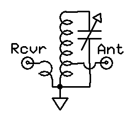
A preselector is a name for an electronic device that connects between a radio antenna and a radio receiver. The preselector is a band-pass filter that blocks troublesome out-of-tune frequencies from passing through from the antenna into the radio receiver that otherwise would be directly connected to the antenna.
A reed receiver or tuned reed receiver (US) was a form of multi-channel signal decoder used for early radio control systems. It uses a simple electromechanical device or 'resonant reed' to demodulate the signal, in effect a receive-only modem. The encoding used is a simple form of frequency-shift keying.

A shortwave radio receiver is a radio receiver that can receive one or more shortwave bands, between 1.6 and 30 MHz. A shortwave radio receiver often receives other broadcast bands, such as FM radio, Longwave and Mediumwave. Shortwave radio receivers are often used by dedicated hobbyists called shortwave listeners.
References
- ↑ Joseph Carr, Antenna Toolkit Elsevier, 2001 ISBN 0080493882, page 193
- ↑ Tony Dorbuck (ed.), The Radio Amateur's Handbook, Fifty Fifth Edition, American Radio Relay League, 1977 no ISBN, p. 259
- ↑ http://www.historywebsite.co.uk/Museum/Engineering/Electronics/AJSSymphony/Symphony.htm The A.J.S. Symphony Seven Receiver - Inside Out, retrieved January 31, 2018
| | This electronics-related article is a stub. You can help Wikipedia by expanding it. |