Frame Relay is a standardized wide area network (WAN) technology that specifies the physical and data link layers of digital telecommunications channels using a packet switching methodology. Originally designed for transport across Integrated Services Digital Network (ISDN) infrastructure, it may be used today in the context of many other network interfaces.

Synchronous Optical Networking (SONET) and Synchronous Digital Hierarchy (SDH) are standardized protocols that transfer multiple digital bit streams synchronously over optical fiber using lasers or highly coherent light from light-emitting diodes (LEDs). At low transmission rates data can also be transferred via an electrical interface. The method was developed to replace the plesiochronous digital hierarchy (PDH) system for transporting large amounts of telephone calls and data traffic over the same fiber without the problems of synchronization.

The T-carrier is a member of the series of carrier systems developed by AT&T Bell Laboratories for digital transmission of multiplexed telephone calls.

In computer networking, Fast Ethernet physical layers carry traffic at the nominal rate of 100 Mbit/s. The prior Ethernet speed was 10 Mbit/s. Of the Fast Ethernet physical layers, 100BASE-TX is by far the most common.

A serial port is a serial communication interface through which information transfers in or out sequentially one bit at a time. This is in contrast to a parallel port, which communicates multiple bits simultaneously in parallel. Throughout most of the history of personal computers, data has been transferred through serial ports to devices such as modems, terminals, various peripherals, and directly between computers.

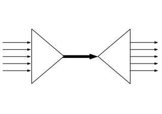
In fiber-optic communications, wavelength-division multiplexing (WDM) is a technology which multiplexes a number of optical carrier signals onto a single optical fiber by using different wavelengths of laser light. This technique enables bidirectional communications over a single strand of fiber as well as multiplication of capacity.
The data link layer, or layer 2, is the second layer of the seven-layer OSI model of computer networking. This layer is the protocol layer that transfers data between nodes on a network segment across the physical layer. The data link layer provides the functional and procedural means to transfer data between network entities and may also provide the means to detect and possibly correct errors that can occur in the physical layer.

A controller area network (CAN) is a vehicle bus standard designed to enable efficient communication primarily between electronic control units (ECUs). Originally developed to reduce the complexity and cost of electrical wiring in automobiles through multiplexing, the CAN bus protocol has since been adopted in various other contexts. This broadcast-based, message-oriented protocol ensures data integrity and prioritization through a process called arbitration, allowing the highest priority device to continue transmitting if multiple devices attempt to send data simultaneously, while others back off. Its reliability is enhanced by differential signaling, which mitigates electrical noise. Common versions of the CAN protocol include CAN 2.0, CAN FD, and CAN XL which vary in their data rate capabilities and maximum data payload sizes.
In computer networking, cut-through switching, also called cut-through forwarding is a method for packet switching systems, wherein the switch starts forwarding a frame before the whole frame has been received, normally as soon as the destination address and outgoing interface is determined. Compared to store and forward, this technique reduces latency through the switch and relies on the destination devices for error handling. Pure cut-through switching is only possible when the speed of the outgoing interface is at least equal or higher than the incoming interface speed.
Spatial Reuse Protocol is a networking protocol developed by Cisco. It is a link layer protocol for ring-based packet internetworking that is commonly used in optical fiber ring networks. Ideas from the protocol are reflected in parts of the IEEE 802.17 Resilient Packet Ring (RPR) standard.
The STM-1 is the SDH ITU-T fiber optic network transmission standard. It has a bit rate of 155.52 Mbit/s. Higher levels go up by a factor of 4 at a time: the other currently supported levels are STM-4, STM-16, STM-64 and STM-256. Above STM-256 wavelength-division multiplexing (WDM) is commonly used in submarine cabling.
Signalling System R2 is a signalling protocol for telecommunications that was in use from the 1960s mostly in Europe, and later also in Latin America, Asia, and Australia, to convey exchange information between two telephone switching systems for establishing a telephone call via a telephone trunk. It is suitable for signaling on analog as well as digital circuits.
Alarm indication signal (AIS) is a signal transmitted by an intermediate element of a multi-node transport circuit that is part of a concatenated communications system to alert the receiving end of the circuit that a segment of the end-to-end link has failed at a logical or physical level, even if the system it is directly connected to is still working. The AIS replaces the failed data, allowing the higher order system in the concatenation to maintain its transmission framing integrity. Downstream intermediate elements of the transport circuit propagate the AIS onwards to the destination element.

IEEE Standard 1355-1995, IEC 14575, or ISO 14575 is a data communications standard for Heterogeneous Interconnect (HIC).
A digital cross-connect system is a piece of circuit-switched network equipment, used in telecommunications networks, that allows lower-level TDM bit streams, such as DS0 bit streams, to be rearranged and interconnected among higher-level TDM signals, such as DS1 bit streams. DCS units are available that operate on both older T-carrier/E-carrier bit streams, as well as newer SONET/SDH bit streams.
Dynamic Packet Transport (DPT) is a Cisco transport protocol designed for use in optical fiber ring networks. In overview, it is quite similar to POS and DTM. It was one of the major influences on the Resilient Packet Ring/802.17 standard.
In telecommunications, subnetwork connection protection (SNCP), is a type of protection mechanism associated with synchronous optical networks such as synchronous digital hierarchy (SDH).

An optical mesh network is a type of optical telecommunications network employing wired fiber-optic communication or wireless free-space optical communication in a mesh network architecture.
Path protection in telecommunications is an end-to-end protection scheme used in connection oriented circuits in different network architectures to protect against inevitable failures on service providers’ network that might affect the services offered to end customers. Any failure occurred at any point along the path of a circuit will cause the end nodes to move/pick the traffic to/from a new route. Finding paths with protection, especially in elastic optical networks, was considered a difficult problem, but an efficient and optimal algorithm was proposed.
Fast automatic restoration (FASTAR) is an automated fast response system developed and deployed by American Telephone & Telegraph (AT&T) in 1992 for the centralized restoration of its digital transport network. FASTAR automatically reroutes circuits over a spare protection capacity when a fiber-optic cable failure is detected, hence increasing service availability and reducing the impact of the outages in the network. Similar in operation is real-time restoration (RTR), developed and deployed by MCI and used in the MCI network to minimize the effects of a fiber cut.


