Related Research Articles

A truss is an assembly of beams or other elements that creates a rigid structure. In engineering, a truss is a structure that "consists of two-force members only, where the members are organized so that the assemblage as a whole behaves as a single object". A "two-force member" is a structural component where force is applied to only two points. Although this rigorous definition allows the members to have any shape connected in any stable configuration, trusses typically comprise five or more triangular units constructed with straight members whose ends are connected at joints referred to as nodes.
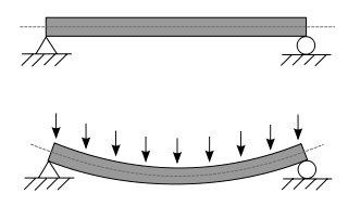
A beam is a structural element that primarily resists loads applied laterally to the beam's axis. Its mode of deflection is primarily by bending. The loads applied to the beam result in reaction forces at the beam's support points. The total effect of all the forces acting on the beam is to produce shear forces and bending moments within the beam, that in turn induce internal stresses, strains and deflections of the beam. Beams are characterized by their manner of support, profile, equilibrium conditions, length, and their material.
In engineering, buckling is the sudden change in shape of a structural component under load such as the bowing of a column under compression or the wrinkling of a plate under shear. If a structure is subjected to a gradually increasing load, when the load reaches a critical level, a member may suddenly change shape and the structure and component is said to have buckled.
Flexural rigidity is defined as the force couple required to bend a fixed non-rigid structure in one unit of curvature or it can be defined as the resistance offered by a structure while undergoing bending.

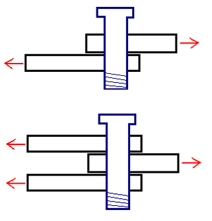
An I-beam, also known as H-beam, w-beam, universal beam (UB), rolled steel joist (RSJ), or double-T, is a beam with an I or H-shaped cross-section. The horizontal elements of the I are flanges, and the vertical element is the "web". I-beams are usually made of structural steel and are used in construction and civil engineering.

Portal frame structures are designed to span between supports and rely on fixed joints with moment resisting capacity where vertical supports connect to horizontal beams or trusses. Portal frame structures can be constructed using a variety of materials and methods. These include steel, reinforced concrete and laminated timber such as glulam. The connections between the columns and the rafters are designed to be moment-resistant, i.e. they can carry bending forces. "They were first developed in the 1960s, and have now become the most common form of enclosure for spans of 20 to 60 m"
This is an alphabetical list of articles pertaining specifically to structural engineering. For a broad overview of engineering, please see List of engineering topics. For biographies please see List of engineers.
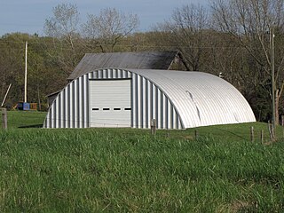
A steel building is a metal structure fabricated with steel for the internal support and for exterior cladding, as opposed to steel framed buildings which generally use other materials for floors, walls, and external envelope. Steel buildings are used for a variety of purposes including storage, work spaces and living accommodation. They are classified into specific types depending on how they are used.
The staggered truss system is a type of structural steel framing used in high-rise buildings. The system consists of a series of story-high trusses spanning the total width between two rows of exterior columns and arranged in a staggered pattern on adjacent column lines. William LeMessurier, the founder Cambridge, Massachusetts engineering firm LeMessurier Consultants has been credited in developing this award winning system as part of his research at the Massachusetts Institute of Technology.
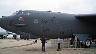
Steel design, or more specifically, structural steel design, is an area of structural engineering used to design steel structures. These structures include schools, houses, bridges, commercial centers, tall buildings, warehouses, aircraft, ships and stadiums. The design and use of steel frames are commonly employed in the design of steel structures. More advanced structures include steel plates and shells.
Reinforced Impact Safety Evolution (RISE) or Realized Impact Safety Evolution is the brand name of Mitsubishi's patented safety body construction system. It was first introduced in the 1996 Mitsubishi Galant. Initially designed to improve passive safety, the system has subsequently been developed to electronically integrate every aspect of car's active and passive safety features.
The moment distribution method is a structural analysis method for statically indeterminate beams and frames developed by Hardy Cross. It was published in 1930 in an ASCE journal. The method only accounts for flexural effects and ignores axial and shear effects. From the 1930s until computers began to be widely used in the design and analysis of structures, the moment distribution method was the most widely practiced method.
The slope deflection method is a structural analysis method for beams and frames introduced in 1914 by George A. Maney. The slope deflection method was widely used for more than a decade until the moment distribution method was developed. In the book, "The Theory and Practice of Modern Framed Structures", written by J.B Johnson, C.W. Bryan and F.E. Turneaure, it is stated that this method was first developed,"by Professor Otto Mohr in Germany, and later developed independently by Professor G.A. Maney". According to this book, professor Otto Mohr introduced this method for the first time in his book,"Evaluation of Trusses with Rigid Node Connections" or "Die Berechnung der Fachwerke mit Starren Knotenverbindungen".
Section modulus is a geometric property for a given cross-section used in the design of beams or flexural members. Other geometric properties used in design include area for tension and shear, radius of gyration for compression, and moment of inertia and polar moment of inertia for stiffness. Any relationship between these properties is highly dependent on the shape in question. Equations for the section moduli of common shapes are given below. There are two types of section moduli, the elastic section modulus and the plastic section modulus. The section moduli of different profiles can also be found as numerical values for common profiles in tables listing properties of such.
In structural engineering, the P-Δ or P-delta effect refers to the abrupt changes in ground shear, overturning moment, and/or the axial force distribution at the base of a sufficiently tall structure or structural component when it is subject to a critical lateral displacement. A distinction can be made between P-delta effects on a multi-tiered building, written as P-Δ, and the effects on members deflecting within a tier, written as P-δ.
Structural engineering depends upon a detailed knowledge of loads, physics and materials to understand and predict how structures support and resist self-weight and imposed loads. To apply the knowledge successfully structural engineers will need a detailed knowledge of mathematics and of relevant empirical and theoretical design codes. They will also need to know about the corrosion resistance of the materials and structures, especially when those structures are exposed to the external environment.
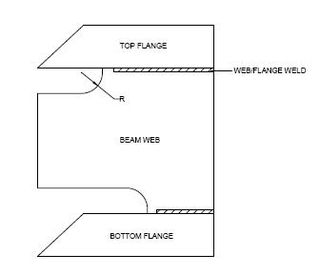
The weld access hole or rat hole is a structural engineering technique in which a part of the web of an I-beam or T-beam is cut out at the end or ends of the beam. The hole in the web allows a welder to weld the flange to another part of the structure with a continuous weld the full width on both top and bottom sides of the flange. Without the weld access hole, the middle of the flange would be blocked by the web and inaccessible for welding.
A buckling-restrained brace (BRB) is a structural brace in a building, designed to allow the building to withstand cyclical lateral loadings, typically earthquake-induced loading. It consists of a slender steel core, a concrete casing designed to continuously support the core and prevent buckling under axial compression, and an interface region that prevents undesired interactions between the two. Braced frames that use BRBs – known as buckling-restrained braced frames, or BRBFs – have significant advantages over typical braced frames.
Moment-resisting frame is a rectilinear assemblage of beams and columns, with the beams rigidly connected to the columns.
Structural support is a part of a building or structure providing the necessary stiffness and strength in order to resist the internal forces and guide them safely to the ground. External loads that act on buildings cause internal forces in building support structures. Supports can be either at the end or at any intermediate point along a structural member or a constituent part of a building and they are referred to as connections, joints or restraints.
References
- Specification for Structural Steel Buildings (ANSI/AISC 360-16) (PDF). American Institute of Steel Construction (AISC). July 7, 2016. Retrieved 2018-01-27.
| This article about a civil engineering topic is a stub. You can help Wikipedia by expanding it. |
| This architecture-related article is a stub. You can help Wikipedia by expanding it. |
| This engineering-related article is a stub. You can help Wikipedia by expanding it. |