Related Research Articles

A Fresnel zone, named after physicist Augustin-Jean Fresnel, is one of a series of confocal prolate ellipsoidal regions of space between and around a transmitter and a receiver. The primary wave will travel in a relative straight line from the transmitter to the receiver. Aberrant transmitted radio, sound, or light waves which are transmitted at the same time can follow slightly different paths before reaching a receiver, especially if there are obstructions or deflecting objects between the two. The two waves can arrive at the receiver at slightly different times and the aberrant wave may arrive out of phase with the primary wave due to the different path lengths. Depending on the magnitude of the phase difference between the two waves, the waves can interfere constructively or destructively. The size of the calculated Fresnel zone at any particular distance from the transmitter and receiver can help to predict whether obstructions or discontinuities along the path will cause significant interference.
Path loss, or path attenuation, is the reduction in power density (attenuation) of an electromagnetic wave as it propagates through space. Path loss is a major component in the analysis and design of the link budget of a telecommunication system.
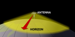
Line-of-sight propagation is a characteristic of electromagnetic radiation or acoustic wave propagation which means waves can only travel in a direct visual path from the source to the receiver without obstacles. Electromagnetic transmission includes light emissions traveling in a straight line. The rays or waves may be diffracted, refracted, reflected, or absorbed by the atmosphere and obstructions with material and generally cannot travel over the horizon or behind obstacles.
Radio propagation is the behavior of radio waves as they travel, or are propagated, from one point to another in vacuum, or into various parts of the atmosphere. As a form of electromagnetic radiation, like light waves, radio waves are affected by the phenomena of reflection, refraction, diffraction, absorption, polarization, and scattering. Understanding the effects of varying conditions on radio propagation has many practical applications, from choosing frequencies for amateur radio communications, international shortwave broadcasters, to designing reliable mobile telephone systems, to radio navigation, to operation of radar systems.
Cabinet is an archive-file format for Microsoft Windows that supports lossless data compression and embedded digital certificates used for maintaining archive integrity. Cabinet files have .cab filename extensions and are recognized by their first four bytes MSCF. Cabinet files were known originally as Diamond files.

NASA WorldWind is an open-source virtual globe. According to the website, "WorldWind is an open source virtual globe API. WorldWind allows developers to quickly and easily create interactive visualizations of 3D globe, map and geographical information. Organizations around the world use WorldWind to monitor weather patterns, visualize cities and terrain, track vehicle movement, analyze geospatial data and educate humanity about the Earth." It was first developed by NASA in 2003 for use on personal computers and then further developed in concert with the open source community since 2004. As of 2017, a web-based version of WorldWind is available online. An Android version is also available.
Multiple frequency-shift keying (MFSK) is a variation of frequency-shift keying (FSK) that uses more than two frequencies. MFSK is a form of M-ary orthogonal modulation, where each symbol consists of one element from an alphabet of orthogonal waveforms. M, the size of the alphabet, is usually a power of two so that each symbol represents log2 M bits.
Waikato Environment for Knowledge Analysis (Weka) is a collection of machine learning and data analysis free software licensed under the GNU General Public License. It was developed at the University of Waikato, New Zealand and is the companion software to the book "Data Mining: Practical Machine Learning Tools and Techniques".
SIMDIS is a software toolset developed by Code 5770 at the US Naval Research Laboratory (NRL). The software provides 2D and 3D interactive graphical and video displays of live and postprocessed simulation, test, and operational data. SIMDIS is a portmanteau of simulation and display.
A wireless site survey, sometimes called an RF site survey or wireless survey, is the process of planning and designing a wireless network, to provide a wireless solution that will deliver the required wireless coverage, data rates, network capacity, roaming capability and quality of service (QoS). The survey usually involves a site visit to test for RF interference, and to identify optimum installation locations for access points. This requires analysis of building floor plans, inspection of the facility, and use of site survey tools. Interviews with IT management and the end users of the wireless network are also important to determine the design parameters for the wireless network.
Naval Surface Warfare Center Crane Division is the principal tenant command located at Naval Support Activity Crane in Indiana.
Weissberger’s modified exponential decay model, or simply, Weissberger’s model, is a radio wave propagation model that estimates the path loss due to the presence of one or more trees in a point-to-point telecommunication link. This model belongs to the category Foliage or Vegetation models.
The Egli model is a terrain model for radio frequency propagation. This model, which was first introduced by John Egli in his 1957 paper, was derived from real-world data on UHF and VHF television transmissions in several large cities. It predicts the total path loss for a point-to-point link. Typically used for outdoor line-of-sight transmission, this model provides the path loss as a single quantity.
The ITU terrain loss model is a radio propagation model that provides a method to predict the median path loss for a telecommunication link. Developed on the basis of diffraction theory, this model predicts the path loss as a function of the height of path blockage and the First Fresnel zone for the transmission link.

VOACAP is a radio propagation model that uses empirical data to predict the point-to-point path loss and coverage of a given transceiver if given as inputs: two antennas, solar weather, and time/date. Written in Fortran, it was originally designed for Voice of America.
The Okumura model is a radio propagation model that was built using data collected in the city of Tokyo, Japan. The model is ideal for using in cities with many urban structures but not many tall blocking structures. The model served as a base for the Hata model.
The Longley–Rice model (LR) is a radio propagation model: a method for predicting the attenuation of radio signals for a telecommunication link in the frequency range of 40 MHz to 100 GHz.

Radio-frequency (RF) engineering is a subset of electrical engineering involving the application of transmission line, waveguide, antenna, radar, and electromagnetic field principles to the design and application of devices that produce or use signals within the radio band, the frequency range of about 20 kHz up to 300 GHz.
This is an index to articles about terms used in discussion of radio propagation.
In the context of mobile radio communication systems, RF planning is the process of assigning frequencies, transmitter locations and parameters to a wireless communications system to evaluate coverage and capacity. Coverage is the distance at which the RF signal has sufficient strength to sustain a call/data session. Capacity relates to the system data rate.
References
- ↑ "SPLAT! KD2BD Software : Name : RF Signal Propagation, Loss, And Terrain analysis tool" (PDF). Qsl.net. Retrieved 2022-01-27.
- ↑ "GitHub - hoche/splat at 2.0-alpha". GitHub. Retrieved 2021-08-17.