Related Research Articles
A schematic, or schematic diagram, is a representation of the elements of a system using abstract, graphic symbols rather than realistic pictures. A schematic usually omits all details that are not relevant to the key information the schematic is intended to convey, and may include oversimplified elements in order to make this essential meaning easier to grasp.
Electronic design automation (EDA), also referred to as electronic computer-aided design (ECAD), is a category of software tools for designing electronic systems such as integrated circuits and printed circuit boards. The tools work together in a design flow that chip designers use to design and analyze entire semiconductor chips. Since a modern semiconductor chip can have billions of components, EDA tools are essential for their design; this article in particular describes EDA specifically with respect to integrated circuits (ICs).

A circuit diagram is a graphical representation of an electrical circuit. A pictorial circuit diagram uses simple images of components, while a schematic diagram shows the components and interconnections of the circuit using standardized symbolic representations. The presentation of the interconnections between circuit components in the schematic diagram does not necessarily correspond to the physical arrangements in the finished device.

Integrated circuit layout, also known IC layout, IC mask layout, or mask design, is the representation of an integrated circuit in terms of planar geometric shapes which correspond to the patterns of metal, oxide, or semiconductor layers that make up the components of the integrated circuit. Originally the overall process was called tapeout as historically early ICs used graphical black crepe tape on mylar media for photo imaging.

Schematic capture or schematic entry is a step in the design cycle of electronic design automation (EDA) at which the electronic diagram, or electronic schematic of the designed electronic circuit is created by a designer. This is done interactively with the help of a schematic capture tool also known as schematic editor.
Place and route is a stage in the design of printed circuit boards, integrated circuits, and field-programmable gate arrays. As implied by the name, it is composed of two steps, placement and routing. The first step, placement, involves deciding where to place all electronic components, circuitry, and logic elements in a generally limited amount of space. This is followed by routing, which decides the exact design of all the wires needed to connect the placed components. This step must implement all the desired connections while following the rules and limitations of the manufacturing process.

CADSTAR is a Windows-based electronic design automation (EDA) software tool for designing and creating schematic diagrams and printed circuit boards (PCBs). It provides engineers with a tool for designing simple or complex, multilayer PCBs. CADSTAR spans schematic capture, variant management, placement, automatic and high-speed routing, signal integrity, power integrity, EMC analysis, design rule checks and production of manufacturing data.

TARGET 3001! is a CAD computer program for EDA and PCB design, developed by Ing.-Büro Friedrich in Germany. It supports the design of electronic schematics, PCBs, and device front panels. It runs under Windows and is available in English, German and French.

OrCAD Systems Corporation was a software company that made OrCAD, a proprietary software tool suite used primarily for electronic design automation (EDA). The software is used mainly by electronic design engineers and electronic technicians to create electronic schematics, perform mixed-signal simulation and electronic prints for manufacturing printed circuit boards. OrCAD was taken over by Cadence Design Systems in 1999 and was integrated with Cadence Allegro since 2005.

XCircuit is a Unix/X11 and Windows program for drawing publication-quality electrical circuit schematic diagrams and related figures and the production of circuit netlists through schematic capture. XCircuit regards circuits as inherently hierarchical and writes both PostScript output and hierarchical SPICE netlists. Circuit components are saved in and retrieved from libraries which are fully editable. XCircuit does not separate artistic expression from circuit drawing; it maintains flexibility in style without compromising the power of schematic capture.
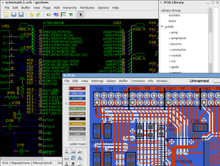
The term gEDA refers to two things:
- A set of software applications used for electronic design released under the GPL. As such, gEDA is an ECAD or EDA application suite. gEDA is mostly oriented towards printed circuit board design. The gEDA applications are often referred to collectively as "the gEDA Suite".
- The collaboration of free software/open-source developers who work to develop and maintain the gEDA toolkit. The developers communicate via gEDA mailing lists, and have participated in the annual "Google Summer of Code" event as a single project. This collaboration is often referred to as "the gEDA Project".
The Layout Versus Schematic (LVS) is the class of electronic design automation (EDA) verification software that determines whether a particular integrated circuit layout corresponds to the original schematic or circuit diagram of the design.

NI Multisim is an electronic schematic capture and simulation program which is part of a suite of circuit design programs, along with NI Ultiboard. Multisim is one of the few circuit design programs to employ the original Berkeley SPICE based software simulation. Multisim was originally created by a company named Electronics Workbench Group, which is now a division of National Instruments. Multisim includes microcontroller simulation, as well as integrated import and export features to the printed circuit board layout software in the suite, NI Ultiboard.

NI Ultiboard or formerly ULTIboard is an electronic Printed Circuit Board Layout program which is part of a suite of circuit design programs, along with NI Multisim. One of its major features is the Real Time Design Rule Check, a feature that was only offered on expensive work stations in the days when it was introduced. ULTIboard was originally created by a company named Ultimate Technology, which is now a subsidiary of National Instruments. Ultiboard includes a 3D PCB viewing mode, as well as integrated import and export features to the Schematic Capture and Simulation software in the suite, Multisim.

The Electric VLSI Design System is an EDA tool written in the early 1980s by Steven M. Rubin. Electric is used to construct logic wire schematics and to perform analysis of integrated circuit layout. It can also handle hardware description languages such as VHDL and Verilog. The system has many analysis and synthesis tools, including Design rule checking, Simulation, Routing, Layout vs. Schematic, Logical Effort, and more.

Electronic circuit simulation uses mathematical models to replicate the behavior of an actual electronic device or circuit. Simulation software allows for modeling of circuit operation and is an invaluable analysis tool. Due to its highly accurate modeling capability, many colleges and universities use this type of software for the teaching of electronics technician and electronics engineering programs. Electronics simulation software engages its users by integrating them into the learning experience. These kinds of interactions actively engage learners to analyze, synthesize, organize, and evaluate content and result in learners constructing their own knowledge.
DesignSpark PCB is a free electronic design automation software package for printed circuit boards. Although there is no charge for the software, the user must register with the website to unlock the program and it displays advertisements which must be acknowledged before the user can begin working.
Pulsonix is an electronic design automation (EDA) software suite for schematic capture and PCB design. It is produced by WestDev, which is headquartered in Gloucestershire, England, with additional sales and distribution offices overseas. It was first released in 2001, and runs on Windows.
EasyEDA is a web-based EDA tool suite that enables hardware engineers to design, simulate, share - publicly and privately - and discuss schematics, simulations and printed circuit boards. Other features include the creation of a bill of materials, Gerber files and pick and place files and documentary outputs in PDF, PNG and SVG formats.
The Proteus Design Suite is a proprietary software tool suite used primarily for electronic design automation. The software is used mainly by electronic design engineers and technicians to create schematics and electronic prints for manufacturing printed circuit boards.
References
- Clein, Dan. (2000). CMOS IC Layout. Newnes. ISBN 0-7506-7194-7