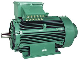
An electric motor is a machine that converts electrical energy into mechanical energy. Most electric motors operate through the interaction between the motor's magnetic field and electric current in a wire winding to generate force in the form of torque applied on the motor's shaft. An electric generator is mechanically identical to an electric motor, but operates in reverse, converting mechanical energy into electrical energy.

A power inverter, inverter, or invertor is a power electronic device or circuitry that changes direct current (DC) to alternating current (AC). The resulting AC frequency obtained depends on the particular device employed. Inverters do the opposite of rectifiers which were originally large electromechanical devices converting AC to DC.

An induction motor or asynchronous motor is an AC electric motor in which the electric current in the rotor that produces torque is obtained by electromagnetic induction from the magnetic field of the stator winding. An induction motor therefore needs no electrical connections to the rotor. An induction motor's rotor can be either wound type or squirrel-cage type.

A linear induction motor (LIM) is an alternating current (AC), asynchronous linear motor that works by the same general principles as other induction motors but is typically designed to directly produce motion in a straight line. Characteristically, linear induction motors have a finite primary or secondary length, which generates end-effects, whereas a conventional induction motor is arranged in an endless loop.

A synchronous electric motor is an AC electric motor in which, at steady state, the rotation of the shaft is synchronized with the frequency of the supply current; the rotation period is exactly equal to an integer number of AC cycles. Synchronous motors use electromagnets as the stator of the motor which create a magnetic field that rotates in time with the oscillations of the current. The rotor with permanent magnets or electromagnets turns in step with the stator field at the same rate and as a result, provides the second synchronized rotating magnet field. Doubly fed synchronous motors use independently-excited multiphase AC electromagnets for both rotor and stator.

A brushless DC electric motor (BLDC), also known as an electronically commutated motor, is a synchronous motor using a direct current (DC) electric power supply. It uses an electronic controller to switch DC currents to the motor windings producing magnetic fields that effectively rotate in space and which the permanent magnet rotor follows. The controller adjusts the phase and amplitude of the current pulses that control the speed and torque of the motor. It is an improvement on the mechanical commutator (brushes) used in many conventional electric motors.

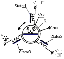
A synchro is, in effect, a transformer whose primary-to-secondary coupling may be varied by physically changing the relative orientation of the two windings. Synchros are often used for measuring the angle of a rotating machine such as an antenna platform or transmitting rotation. In its general physical construction, it is much like an electric motor. The primary winding of the transformer, fixed to the rotor, is excited by an alternating current, which by electromagnetic induction causes voltages to appear between the Y-connected secondary windings fixed at 120 degrees to each other on the stator. The voltages are measured and used to determine the angle of the rotor relative to the stator.

Power electronics is the application of electronics to the control and conversion of electric power.

A rotary converter is a type of electrical machine which acts as a mechanical rectifier, inverter or frequency converter.

A variable-frequency drive is a type of AC motor drive that controls speed and torque by varying the frequency of the input electricity. Depending on its topology, it controls the associated voltage or current variation.

A cycloconverter (CCV) or a cycloinverter converts a constant amplitude, constant frequency AC waveform to another AC waveform of a lower frequency by synthesizing the output waveform from segments of the AC supply without an intermediate DC link. There are two main types of CCVs, circulating current type or blocking mode type, most commercial high power products being of the blocking mode type.

A motor drive is a physical system that includes a motor. An adjustable speed motor drive is a system that includes a motor that has multiple operating speeds. A variable speed motor drive is a system that includes a motor that is continuously variable in speed. If the motor is generating electrical energy rather than using it, the motor drive could be called a generator drive but is often still referred to as a motor drive.

A rotary phase converter, abbreviated RPC, is an electrical machine that converts power from one polyphase system to another, converting through rotary motion. Typically, single-phase electric power is used to produce three-phase electric power locally to run three-phase loads in premises where only single-phase is available.

An AC motor is an electric motor driven by an alternating current (AC). The AC motor commonly consists of two basic parts, an outside stator having coils supplied with alternating current to produce a rotating magnetic field, and an inside rotor attached to the output shaft producing a second rotating magnetic field. The rotor magnetic field may be produced by permanent magnets, reluctance saliency, or DC or AC electrical windings.
Direct torque control (DTC) is one method used in variable-frequency drives to control the torque of three-phase AC electric motors. This involves calculating an estimate of the motor's magnetic flux and torque based on the measured voltage and current of the motor.
Doubly fed electric machines, Doubly fed induction generator (DFIG), or slip-ring generators, are electric motors or electric generators, where both the field magnet windings and armature windings are separately connected to equipment outside the machine.

The rotor is a moving component of an electromagnetic system in the electric motor, electric generator, or alternator. Its rotation is due to the interaction between the windings and magnetic fields which produces a torque around the rotor's axis.
In electrical engineering, electric machine is a general term for machines using electromagnetic forces, such as electric motors, electric generators, and others. They are electromechanical energy converters: an electric motor converts electricity to mechanical power while an electric generator converts mechanical power to electricity. The moving parts in a machine can be rotating or linear. While transformers are occasionally called "static electric machines", since they do not have moving parts, generally they are not considered "machines", but as electrical devices "closely related" to the electrical machines.
Vector control, also called field-oriented control (FOC), is a variable-frequency drive (VFD) control method in which the stator currents of a three-phase AC or brushless DC electric motor are identified as two orthogonal components that can be visualized with a vector. One component defines the magnetic flux of the motor, the other the torque. The control system of the drive calculates the corresponding current component references from the flux and torque references given by the drive's speed control. Typically proportional-integral (PI) controllers are used to keep the measured current components at their reference values. The pulse-width modulation of the variable-frequency drive defines the transistor switching according to the stator voltage references that are the output of the PI current controllers.

The switched reluctance motor (SRM) is a type of reluctance motor. Unlike brushed DC motors, power is delivered to windings in the stator (case) rather than the rotor. This simplifies mechanical design because power does not have to be delivered to the moving rotor, which eliminates the need for a commutator. However it complicates the electrical design, because a switching system must deliver power to the different windings and limit torque ripple. Sources disagree on whether it is a type of stepper motor.


