
An amplifier, electronic amplifier or (informally) amp is an electronic device that can increase the magnitude of a signal. It is a two-port electronic circuit that uses electric power from a power supply to increase the amplitude of a signal applied to its input terminals, producing a proportionally greater amplitude signal at its output. The amount of amplification provided by an amplifier is measured by its gain: the ratio of output voltage, current, or power to input. An amplifier is defined as a circuit that has a power gain greater than one.

An audio power amplifier amplifies low-power electronic audio signals, such as the signal from a radio receiver or an electric guitar pickup, to a level that is high enough for driving loudspeakers or headphones. Audio power amplifiers are found in all manner of sound systems including sound reinforcement, public address, home audio systems and musical instrument amplifiers like guitar amplifiers. It is the final electronic stage in a typical audio playback chain before the signal is sent to the loudspeakers.
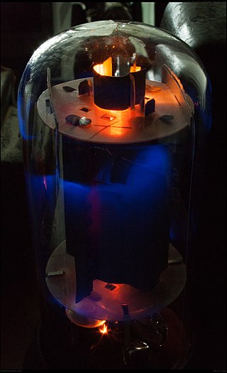
A valve amplifier or tube amplifier is a type of electronic amplifier that uses vacuum tubes to increase the amplitude or power of a signal. Low to medium power valve amplifiers for frequencies below the microwaves were largely replaced by solid state amplifiers in the 1960s and 1970s. Valve amplifiers can be used for applications such as guitar amplifiers, satellite transponders such as DirecTV and GPS, high quality stereo amplifiers, military applications and very high power radio and UHF television transmitters.

A differential amplifier is a type of electronic amplifier that amplifies the difference between two input voltages but suppresses any voltage common to the two inputs. It is an analog circuit with two inputs and and one output , in which the output is ideally proportional to the difference between the two voltages:

The Armstrong oscillator is an electronic oscillator circuit which uses an inductor and capacitor to generate an oscillation. The Meissner patent from 1913 describes a device for generating electrical vibrations, a radio transmitter used for On–off keying. Edwin Armstrong presented in 1915 some recent developments in the Audion receiver. His circuits improved radio frequency reception. Meissner used a Lieben-Reisz-Strauss tube, Armstrong used a de Forest Audion tube. Both circuits are sometimes called a tickler oscillator because the distinguishing feature is that the feedback signal needed to produce oscillations is magnetically coupled into the tank inductor by a "tickler coil" (L2, right). Assuming the coupling is weak but sufficient to sustain oscillation, the oscillation frequency f is determined primarily by the LC circuit and is approximately given by

A push–pull amplifier is a type of electronic circuit that uses a pair of active devices that alternately supply current to, or absorb current from, a connected load. This kind of amplifier can enhance both the load capacity and switching speed.

A beam tetrode, sometimes called a beam power tube, is a type of vacuum tube or thermionic valve that has two grids and forms the electron stream from the cathode into multiple partially collimated beams to produce a low potential space charge region between the anode and screen grid to return anode secondary emission electrons to the anode when the anode potential is less than that of the screen grid. Beam tetrodes are usually used for power amplification, from audio frequency to radio frequency. The beam tetrode produces greater output power than a triode or pentode with the same anode supply voltage. The first beam tetrode marketed was the Marconi N40, introduced in 1935. Beam tetrodes manufactured and used in the 21st century include the 4CX250B, KT66 and variants of the 6L6.
A linear amplifier is an electronic circuit whose output is proportional to its input, but capable of delivering more power into a load. The term usually refers to a type of radio-frequency (RF) power amplifier, some of which have output power measured in kilowatts, and are used in amateur radio. Other types of linear amplifier are used in audio and laboratory equipment. Linearity refers to the ability of the amplifier to produce signals that are accurate copies of the input. A linear amplifier responds to different frequency components independently, and tends not to generate harmonic distortion or intermodulation distortion. No amplifier can provide perfect linearity however, because the amplifying devices—transistors or vacuum tubes—follow nonlinear transfer function and rely on circuitry techniques to reduce those effects. There are a number of amplifier classes providing various trade-offs between implementation cost, efficiency, and signal accuracy.

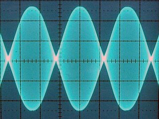
Clipping is a form of waveform distortion that occurs when an amplifier is overdriven and attempts to deliver an output voltage or current beyond its maximum capability. Driving an amplifier into clipping may cause it to output power in excess of its power rating.

In electronics, the Sziklai pair, also known as a complementary feedback pair, is a configuration of two bipolar transistors, similar to a Darlington pair. In contrast to the Darlington arrangement, the Sziklai pair has one NPN and one PNP transistor, and so it is sometimes also called the "complementary Darlington". The configuration is named for George C. Sziklai, thought to be its inventor.
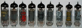
The EL84 is a vacuum tube of the power pentode type. It is used in the power-output-stages of audio-amplifiers, most commonly now in guitar amplifiers, but originally in radios. The EL84 is smaller and more sensitive than the octal 6V6 that was widely used around the world until the 1960s. An interchangeable North American type is the 6BQ5.
A valve audio amplifier (UK) or vacuum tube audio amplifier (US) is a valve amplifier used for sound reinforcement, sound recording and reproduction.
A direct-coupled amplifier or DC amplifier is a type of amplifier in which the output of one stage of the amplifier is coupled to the input of the next stage in such a way as to permit signals with zero frequency, also referred to as direct current, to pass from input to output. This is an application of the more general direct coupling. It was invented by Harold J Paz and Francis P. Keiper Jr. in 1955. It displaced the triode vacuum tube amplifier designed by Lee de Forest. Almost all vacuum tube circuit designs are now replaced with direct coupled transistor circuit design. It is the first transistor amplifier design that did not include coupling capacitors. The direct-coupled amplifier allowed analog circuits to be built smaller with the elimination of coupling capacitors and removed the lower frequency limitation that is dependent on capacitors.

A multistage amplifier is an electronic amplifier consisting of two or more single-stage amplifiers connected together. In this context, a single stage is an amplifier containing only a single transistor or other active device. The most common reason for using multiple stages is to increase the gain of the amplifier in applications where the input signal is very small, for instance in radio receivers. In these applications a single stage has insufficient gain by itself. In some designs it is possible to obtain more desirable values of other parameters such as input resistance and output resistance.

In electronics, biasing is the setting of DC operating conditions of an electronic component that processes time-varying signals. Many electronic devices, such as diodes, transistors and vacuum tubes, whose function is processing time-varying (AC) signals, also require a steady (DC) current or voltage at their terminals to operate correctly. This current or voltage is called bias. The AC signal applied to them is superposed on this DC bias current or voltage.
Ultra-linear electronic circuits are those used to couple a tetrode or pentode vacuum-tube to a load.
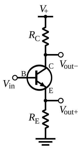
A phase splitter is a device that separates a signal into multiple phases.

Tube sound is the characteristic sound associated with a vacuum tube amplifier, a vacuum tube-based audio amplifier. At first, the concept of tube sound did not exist, because practically all electronic amplification of audio signals was done with vacuum tubes and other comparable methods were not known or used. After introduction of solid state amplifiers, tube sound appeared as the logical complement of transistor sound, which had some negative connotations due to crossover distortion in early transistor amplifiers. However, solid state amplifiers have been developed to be flawless and the sound is later regarded neutral compared to tube amplifiers. Thus the tube sound now means 'euphonic distortion.' The audible significance of tube amplification on audio signals is a subject of continuing debate among audio enthusiasts.
A Virtual Valve Amplifier (VVA) is software algorithm designed and sold by Diamond Cut Productions, Inc. for simulating the sound of various valve amplifier designs. It can be found within their DC8 and Forensics8 software programs.
In electronics, power amplifier classes are letter symbols applied to different power amplifier types. The class gives a broad indication of an amplifier's characteristics and performance. The first three classes are related to the time period that the active amplifier device is passing current, expressed as a fraction of the period of a signal waveform applied to the input. This metric is known as conduction angle (θ). A class A amplifier is conducting through all the period of the signal (θ=360°); Class B only for one-half the input period (θ=180°), class C for much less than half the input period (θ<180°). Class D amplifiers operate their output device in a switching manner; the fraction of the time that the device is conducting may be adjusted so a pulse-width modulation output can be obtained from the stage.