Sliding criterion (geotechnical engineering)

Last updated

The sliding criterion (discontinuity) is a tool to estimate easily the shear strength properties of a discontinuity in a rock mass based on visual and tactile (i.e. by feeling) characterization of the discontinuity. [1] [2] [3] [4] The shear strength of a discontinuity is important in, for example, tunnel, foundation, or slope engineering, but also stability of natural slopes is often governed by the shear strength along discontinuities.

Contents

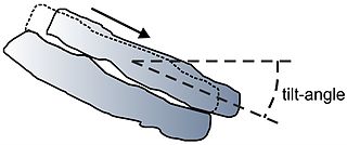
The sliding-angle is based on the ease with which a block of rock material can move over a discontinuity and hence is comparable to the tilt-angle as determined with the tilt test, but on a larger scale. The sliding criterion has been developed for stresses that would occur in slopes between 2 and 25 metres (6.6 and 82.0 ft), hence, in the order of maximum 0.6 megapascals (87 psi). The sliding criterion is based on back analyses of slope instability and earlier work of ISRM [5] and Laubscher. [6] The sliding criterion is part of the Slope Stability Probability Classification (SSPC) [3] system for slope stability analyses.

Table 1. Discontinuity characterization & factors.
characterizationfactor
Roughness large scale (Rl)wavy1.00
slightly wavy0.95
curved0.85
slightly curved0.80
straight0.75
Roughness small scale (Rs)rough stepped/irregular0.95
smooth stepped0.90
polished stepped0.85
rough undulating0.80
smooth undulating0.75
polished undulating0.70
rough planar0.65
smooth planar0.60
polished planar0.55
Infill material (Im)cemented/cemented infill1.07
no infill - surface staining only1.00
non-softening & sheared material, e.g. free of clay, talccoarse0.95
medium0.90
fine0.85
softening & soft-sheared material, e.g. clay, talccoarse0.75
medium0.65
fine0.55
gouge < irregularities0.42
gouge > irregularities0.17
flowing material0.05
Karst (Ka)none1.00
karst0.92

Sliding-angle

The sliding-angle is calculated as follows:


where sliding-angle is in degrees, and
Rl = roughness large scale
Rs = roughness small scale
Im = infill material in the discontinuity
Ka = karst; presence of karst (solution) features along the discontinuity

(The values for the parameters are listed in table 1 and explained below)

Figure 1. Large scale example roughness graphs. SlidingcriterionRl.jpg
Figure 1. Large scale example roughness graphs.

Roughness large scale (Rl)

The roughness large scale (Rl) is based on visual comparison of the trace (with a length of about 1 m) or surface (with an area of about 1 x 1 m2 of a discontinuity with the example graphs in figure 1. This results in a descriptive term: wavy, slightly wavy, curved, slightly curved, or straight. The corresponding factor for Rl is listed in table 1.
The roughness large scale (Rl) contributes only to the friction along the discontinuity when the walls on both sides of the discontinuity are fitting, i.e. the asperities on both discontinuity walls match. If the discontinuity is non-fitting, the factor Rl = 0.75.

Figure 2. Small scale example roughness graphs. SlidingcriterionRs.jpg
Figure 2. Small scale example roughness graphs.

Roughness small scale (Rs)

The roughness small scale (Rs) is established visually and tactile (by feeling). The first term rough, smooth, or polished is established by feeling the surface of the discontinuity; rough hurts when fingers are moved over the surface with some (little) force, smooth feels that there is resistance to the fingers, while polished gives a feeling about similar to the surface of glass.
The second term is established visually. The trace (with a length of about 0.2 m) or surface (with an area of about 0.2 x 0.2 m2 of a discontinuity is compared with the example graphs in figure 2; this gives stepped, undulating, or planar. The two terms of visual and tactile give a combined term and the corresponding factor is listed in table 1.
The visual part of the roughness small scale (Rs) contributes only to the friction along the discontinuity if the walls on both sides of the discontinuity are fitting, i.e. the asperities on both discontinuity walls match. If the discontinuity is non-fitting, the visual part of the roughness small scale (Rs) should be taken as planar for the calculation of the sliding-angle, and hence, the roughness small scale (Rs) can be only rough planar, smooth planar, or polished planar.

Infill in discontinuity (Im)

Infill material in a discontinuity has often a marked influence on the shear characteristics. The different options for infill material are listed in table 1, and below follows a short explanation for each option.

Cemented discontinuity or cemented infill

A cemented discontinuity or a discontinuity with cemented infill has higher shear strength than a non-cemented discontinuity if the cement or cemented infill is bonded to both discontinuity walls. Note that cement and cement bounds that are stronger than the surrounding intact rock ceases the discontinuity to be a mechanical plane of weakness, and, hence, the 'sliding-angle' has no validity.

No infill

No infill describes a discontinuity that may have coated walls but no other infill.

Non-softening infill

Non-softening infill material is material that does not change in shear characteristics under the influence of water nor under the influence of shear displacement. The material may break but no greasing effect will occur. The material particles can roll but this is considered to be of minor influence because, after small displacements, the material particles generally will still be very angular. This is further sub-divided in coarse, medium, and fine for the size of the grains in the infill material or the size of the grains or minerals in the discontinuity wall. The larger of the two should be used for the description. The thickness of the infill can be very thin, sometimes not more than a dust coating.

Softening infill

Softening infill material will under the influence of water or displacements, attain in lower shear strength and will act as a lubricating agent. This is further sub-divided in coarse, medium, and fine for the size of the grains in the infill material or the size of the grains or minerals in the discontinuity wall. The larger of the two should be used for the description. The thickness of the infill can be very thin, sometimes not more than a dust coating.

Gouge infill

Gouge infill means a relatively thick and continuous layer of infill material, mainly consisting of clay but may contain rock fragments. The clay material surrounds the rock fragments in the clay completely or partly, so that these are not in contact with both discontinuity walls. A sub-division is made between less thick and thicker than the amplitude of the roughness of the discontinuity walls. If the thickness is less than the amplitude of the roughness, the shear strength will be influenced by the wall material and the discontinuity walls will be in contact after a certain displacement. If the infill is thicker than the amplitude, the friction of the discontinuity is fully governed by the infill.

Flowing material infill

Very weak and not compacted infill in discontinuities flows out of the discontinuities under its own weight or as a consequence of a very small trigger force (such as water pressure, vibrations due to traffic or the excavation process, etc.).

Karst (Ka)

The presence of solution (karst) features along the discontinuity.

See also

Related Research Articles

Geotechnical engineering Scientific study of earth materials in engineering problems

Geotechnical engineering, also known as geotechnics, is the branch of civil engineering concerned with the engineering behavior of earth materials. It uses the principles of soil mechanics and rock mechanics for the solution of its respective engineering problems. It also relies on knowledge of geology, hydrology, geophysics, and other related sciences. Geotechnical (rock) engineering is a subdiscipline of geological engineering.

Landslide Natural disaster involving ground movement

Landslides, also known as landslips, are several forms of mass wasting that may include a wide range of ground movements, such as rockfalls, deep-seated slope failures, mudflows, and debris flows. Landslides occur in a variety of environments, characterized by either steep or gentle slope gradients, from mountain ranges to coastal cliffs or even underwater, in which case they are called submarine landslides. Gravity is the primary driving force for a landslide to occur, but there are other factors affecting slope stability that produce specific conditions that make a slope prone to failure. In many cases, the landslide is triggered by a specific event, although this is not always identifiable.

Mass wasting Geomorphic process by which soil, sand, regolith, and rock move downslope

Mass wasting, also known as slope movement or mass movement, is the geomorphic process by which soil, sand, regolith, and rock move downslope typically as a solid, continuous or discontinuous mass, largely under the force of gravity, frequently with characteristics of a flow as in debris flows and mudflows. Types of mass wasting include creep, slides, flows, topples, and falls, each with its own characteristic features, and taking place over timescales from seconds to hundreds of years. Mass wasting occurs on both terrestrial and submarine slopes, and has been observed on Earth, Mars, Venus and Jupiter's moons Io and Ganymede.

Soil mechanics Branch of soil physics and applied mechanics that describes the behavior of soils

Soil mechanics is a branch of soil physics and applied mechanics that describes the behavior of soils. It differs from fluid mechanics and solid mechanics in the sense that soils consist of a heterogeneous mixture of fluids and particles but soil may also contain organic solids and other matter. Along with rock mechanics, soil mechanics provides the theoretical basis for analysis in geotechnical engineering, a subdiscipline of civil engineering, and engineering geology, a subdiscipline of geology. Soil mechanics is used to analyze the deformations of and flow of fluids within natural and man-made structures that are supported on or made of soil, or structures that are buried in soils. Example applications are building and bridge foundations, retaining walls, dams, and buried pipeline systems. Principles of soil mechanics are also used in related disciplines such as geophysical engineering, coastal engineering, agricultural engineering, hydrology and soil physics.

Rock mass classification systems are used for various engineering design and stability analysis. These are based on empirical relations between rock mass parameters and engineering applications, such as tunnels, slopes, foundations, and excavatability. The first rock mass classification system in geotechnical engineering was proposed in 1946 for tunnels with steel set support.

Foliation (geology)

Foliation in geology refers to repetitive layering in metamorphic rocks. Each layer can be as thin as a sheet of paper, or over a meter in thickness. The word comes from the Latin folium, meaning "leaf", and refers to the sheet-like planar structure. It is caused by shearing forces, or differential pressure. The layers form parallel to the direction of the shear, or perpendicular to the direction of higher pressure. Nonfoliated metamorphic rocks are typically formed in the absence of significant differential pressure or shear. Foliation is common in rocks affected by the regional metamorphic compression typical of areas of mountain belt formation.

A direct shear test is a laboratory or field test used by geotechnical engineers to measure the shear strength properties of soil or rock material, or of discontinuities in soil or rock masses.

Fracture (geology) Geologic structure

A fracture is any separation in a geologic formation, such as a joint or a fault that divides the rock into two or more pieces. A fracture will sometimes form a deep fissure or crevice in the rock. Fractures are commonly caused by stress exceeding the rock strength, causing the rock to lose cohesion along its weakest plane. Fractures can provide permeability for fluid movement, such as water or hydrocarbons. Highly fractured rocks can make good aquifers or hydrocarbon reservoirs, since they may possess both significant permeability and fracture porosity.

Triaxial shear test

A triaxial shear test is a common method to measure the mechanical properties of many deformable solids, especially soil and rock, and other granular materials or powders. There are several variations on the test.

There have been known various classifications of landslides. Broad definitions include forms of mass movement that narrower definitions exclude. For example, the McGraw-Hill Encyclopedia of Science and Technology distinguishes the following types of landslides:

Landslide mitigation refers to several man-made activities on slopes with the goal of lessening the effect of landslides. Landslides can be triggered by many, sometimes concomitant causes. In addition to shallow erosion or reduction of shear strength caused by seasonal rainfall, landslides may be triggered by anthropic activities, such as adding excessive weight above the slope, digging at mid-slope or at the foot of the slope. Often, individual phenomena join together to generate instability over time, which often does not allow a reconstruction of the evolution of a particular landslide. Therefore, landslide hazard mitigation measures are not generally classified according to the phenomenon that might cause a landslide. Instead, they are classified by the sort of slope stabilization method used:

Slope mass rating (SMR) is a rock mass classification scheme developed by Manuel Romana to describe the strength of an individual rock outcrop or slope. The system is founded upon the more widely used RMR scheme, which is modified with quantitative guidelines to the rate the influence of adverse joint orientations.

Slope stability analysis is a static or dynamic, analytical or empirical method to evaluate the stability of earth and rock-fill dams, embankments, excavated slopes, and natural slopes in soil and rock. Slope stability refers to the condition of inclined soil or rock slopes to withstand or undergo movement. The stability condition of slopes is a subject of study and research in soil mechanics, geotechnical engineering and engineering geology. Analyses are generally aimed at understanding the causes of an occurred slope failure, or the factors that can potentially trigger a slope movement, resulting in a landslide, as well as at preventing the initiation of such movement, slowing it down or arresting it through mitigation countermeasures.

A discontinuity in geotechnical engineering is a plane or surface that marks a change in physical or chemical characteristics in a soil or rock mass. A discontinuity can be, for example, a bedding, schistosity, foliation, joint, cleavage, fracture, fissure, crack, or fault plane. A division is made between mechanical and integral discontinuities. Discontinuities may occur multiple times with broadly the same mechanical characteristics in a discontinuity set, or may be a single discontinuity. A discontinuity makes a soil or rock mass anisotropic.

Tilt test (geotechnical engineering)

In geomechanics, a tilt test is a simple test to estimate the shear strength parameters of a discontinuity. Two pieces of rock containing a discontinuity are held in hand or mounted in test equipment with the discontinuity horizontal. The sample is slowly tilted until the top block moves. The angle with the horizontal at onset of movement is called the tilt-angle.

In geotechnical engineering and contact mechanics the term asperity is used to refer to individual features of unevenness (roughness) of the surface of a discontinuity, grain, or particle with heights in the range from approximately 0.1 mm to the order of metres. Below the asperity level, surface interactions are normally considered to be a material property, arising from mechanisms of adhesion and repulsion at the atomic scale.

The Q-system for rock mass classification is developed by Barton, Lien, and Lunde. It expresses the quality of the rock mass in the so-called Q-value, on which are based design and support recommendations for underground excavations.

The shear strength of a discontinuity in a soil or rock mass may have a strong impact on the mechanical behavior of a soil or rock mass. The shear strength of a discontinuity is often considerably lower than the shear strength of the blocks of intact material in between the discontinuities, and therefore influences, for example, tunnel, foundation, or slope engineering, but also the stability of natural slopes. Many slopes, natural and man-made, fail due to a low shear strength of discontinuities in the soil or rock mass in the slope. The deformation characteristics of a soil or rock mass are also influenced by the shear strength of the discontinuities. For example, the modulus of deformation is reduced, and the deformation becomes plastic rather than elastic. This may cause, for example, larger settlement of foundations, which is also permanent even if the load is only temporary. Furthermore, the shear strength of discontinuities influences the stress distribution in a soil or rock mass.

Persistence (discontinuity)

Persistence determines the possibilities of relative movement along a discontinuity in a soil or rock mass in geotechnical engineering. Discontinuities are usually differentiated in persistent, non-persistent, and abutting discontinuities (figure).

Q-slope

The Q-slope method for rock slope engineering and rock mass classification is developed by Barton and Bar. It expresses the quality of the rock mass for slope stability using the Q-slope value, from which long-term stable, reinforcement-free slope angles can be derived.

References

  1. Hack, H.R.G.K.; Price, D.G. (September 25–29, 1995). Fujii, T. (ed.). Determination of discontinuity friction by rock mass classification (PDF). Proceedings 8th International Society for Rock Mechanics (ISRM) congress. 3. Tokyo, Japan: Balkema, Rotterdam, Taylor & Francis. pp. 23–27. ISBN   978-90-5410-576-3.
  2. Hack, R. (1998) [1st edition; 2nd edition 1998]. Slope Stability Probability Classification (SSPC) (PDF). ITC publication 43. Technical University Delft & Twente University - International Institute for Aerospace Survey and Earth Sciences (ITC Enschede), Netherlands. p. 258. ISBN   978-90-6164-154-4.
  3. 1 2 Hack, R.; Price, D.; Rengers, N. (2003). "A new approach to rock slope stability – a probability classification (SSPC)". Bulletin of Engineering Geology and the Environment. 62 (2): 167–184. doi:10.1007/s10064-002-0155-4.
  4. Price, D.G. (2008). De Freitas, M.H. (ed.). Engineering Geology: Principles and Practice. Springer. p. 450. ISBN   978-3-540-29249-4.
  5. ISRM (2007). Ulusay, R.; Hudson, J.A. (eds.). The Blue Book - The Complete ISRM Suggested Methods for Rock Characterization, Testing and Monitoring: 1974-2006. Ankara: ISRM & ISRM Turkish National Group. p. 628. ISBN   978-975-93675-4-1.
  6. Laubscher, D.H. (1990). "A geomechanics classification system for rating of rock mass in mine design". Journal South African Institute of Mining and Metallurgy. 90 (10): 257–273. ISSN   0038-223X.

Further reading