A spectroradiometer is a light measurement tool that is able to measure both the wavelength and amplitude of the light emitted from a light source. Spectrometers discriminate the wavelength based on the position the light hits at the detector array allowing the full spectrum to be obtained with a single acquisition. Most spectrometers have a base measurement of counts which is the un-calibrated reading and is thus impacted by the sensitivity of the detector to each wavelength. By applying a calibration, the spectrometer is then able to provide measurements of spectral irradiance, spectral radiance and/or spectral flux. This data is also then used with built in or PC software and numerous algorithms to provide readings or Irradiance (W/cm2), Illuminance (lux or fc), Radiance (W/sr), Luminance (cd), Flux (Lumens or Watts), Chromaticity, Color Temperature, Peak and Dominant Wavelength. Some more complex spectrometer software packages also allow calculation of PAR μmol/m2/s, Metamerism, and candela calculations based on distance and include features like 2- and 20-degree observer, baseline overlay comparisons, transmission and reflectance.
Spectrometers are available in numerous packages and sizes covering many wavelength ranges. The effective wavelength (spectral) range of a spectrometer is determined not only by the grating dispersion ability but also depends on the detectors' sensitivity range. Limited by the semiconductor's band gap the silicon-based detector responds to 200-1100nm while the InGaAs based detector is sensitive to 900-1700nm (or out to 2500nm with cooling).
Lab/Research spectrometers often cover a broad spectral range from UV to NIR and require a PC. There are also IR Spectrometers that require higher power to run a cooling system. Many Spectrometers can be optimized for a specific range i.e. UV, or VIS and combined with a second system to allow more precise measurements, better resolution, and eliminate some of the more common errors found in broadband system such as stray light and lack of sensitivity.
Portable devices are also available for numerous spectral ranges covering UV to NIR and offer many different package styles and sizes. Hand held systems with integrated displays typically have built in optics, and an onboard computer with pre-programmed software. Mini spectrometers are also able to be used hand held, or in the lab as they are powered and controlled by a PC and require a USB cable. Input optics may be incorporated or are commonly attached by a fiber optic light guide. There are also micro Spectrometers smaller than a quarter that can be integrated into a system, or used stand alone.
Background
The field of spectroradiometry concerns itself with the measurement of absolute radiometric quantities in narrow wavelength intervals.[1] It is useful to sample the spectrum with narrow bandwidth and wavelength increments because many sources have line structures [2] Most often in spectroradiometry, spectral irradiance is the desired measurement. In practice, the average spectral irradiance is measured, shown mathematically as the approximation:
Where is the spectral irradiance, is the radiant flux of the source (SI unit: watt, W) within a wavelength interval (SI unit: meter, m), incident on the surface area, (SI unit: square meter, m2). The SI unit for spectral irradiance is W/m3. However it is often more useful to measure area in terms of centimeters and wavelength in nanometers, thus submultiples of the SI units of spectral irradiance will be used, for example μW/cm2*nm[3]
Spectral irradiance will vary from point to point on the surface in general. In practice, it is important note how radiant flux varies with direction, the size of the solid angle subtended by the source at each point on the surface, and the orientation of the surface. Given these considerations, it is often more prudent to use a more rigorous form of the equation to account for these dependencies[3]
Note that the prefix "spectral" is to be understood as an abbreviation of the phrase "spectral concentration of" which is understood and defined by the CIE as the "quotient of the radiometric quantity taken over an infinitesimal range on either side of a given wavelength, by the range".[4]
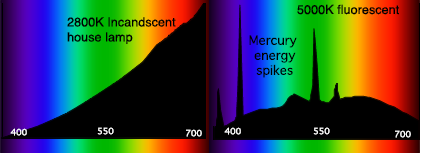
The spectral power distribution (SPD) of a source describes how much flux reaches the sensor over a particular wavelength and area. This effectively expresses the per-wavelength contribution to the radiometric quantity being measured. The SPD of a source is commonly shown as an SPD curve. SPD curves provide a visual representation of the color characteristics of a light source, showing the radiant flux emitted by the source at various wavelengths across the visible spectrum[5] It is also a metric by which we can evaluate a light source's ability to render colors, that is, whether a certain color stimulus can be properly rendered under a given illuminant.
Characteristic spectral power distributions (SPDs) for an incandescent lamp (left) and a fluorescent lamp (right). The horizontal axes are in nanometers and the vertical axes show relative intensity in arbitrary units.
Sources of error
The quality of a given spectroradiometric system is a function of its electronics, optical components, software, power supply, and calibration. Under ideal laboratory conditions and with highly trained experts, it is possible to achieve small (a few tenths to a few percent) errors in measurements. However, in many practical situations, there is the likelihood of errors on the order of 10 percent [3] Several types of error are at play when taking physical measurements. The three basic types of error noted as the limiting factors of accuracy of measurement are random, systematic, and periodic errors [6]
Random errors are variations about that mean. In the case of spectroradiometric measurements, this could be thought of as noise from the detector, internal electronics, or the light source itself. Errors of this type can be combated by longer integration times or multiple scans.
Systematic errors are offsets to the predicted "correct" value. Systematic errors generally occur due to the human component of these measurements, the device itself, or the setup of the experiment. Things such as calibration errors, stray light, and incorrect settings, are all potential issues.
Periodic errors arise from recurrent periodic or pseudo-periodic events. Variations in temperature, humidity, air-motion, or AC interference could all be categorized as periodic error.[6]
In addition to these generic sources of error, a few of the more specific reasons for error in spectroradiometry include:
The multidimensionality of the measurement. The output signal is dependent on several factors, including magnitude of measured flux, its direction, its polarization, and its wavelength distribution.
The inaccuracy of measuring instruments, as well as the standards used to calibrate said instruments, cascaded to create a larger error throughout the entire measurement process, and
The proprietary techniques for reducing multidimensionality and device instability error.[3]
Gamma-scientific, a California-based manufacturer of light measurement devices, lists seven factors affecting the accuracy and performance of their spectroradiometers, due to either the system calibration, the software and power supply, the optics, or the measurement engine itself.[7]
Stray light is unwanted wavelength radiation reaching the incorrect detector element. It generates erroneous electronic counts not related to designed spectral signal for the pixel or element of the detector array. It can come from light scatter and reflection of imperfect optical elements as well as higher order diffraction effects. The second order effect can be removed or at least dramatically reduced, by installing order sorting filters before the detector.
A Si detector's sensitivity to visible and NIR is nearly an order of magnitude larger than that in the UV range. This means that the pixels at the UV spectral position respond to stray light in visible and NIR much more strongly than to their own designed spectral signal. Therefore, the stray light impacts in UV region are much more significant as compared to visible and NIR pixels. This situation gets worse the shorter the wavelength.
When measuring broad band light with small fraction of UV signals, the stray light impact can sometimes be dominant in the UV range since the detector pixels are already struggling to get enough UV signals from the source. For this reason, calibration using a QTH standard lamp can have huge errors (more than 100%) below 350nm and a deuterium standard lamp is required for more accurate calibration in this region. In fact, absolute light measurement in the UV region can have large errors even with the correct calibration when majority of the electronic counts in these pixels is result of the stray light (longer wavelength strikes instead of the actual UV light).
Calibration errors
There are numerous companies that offer calibration for spectrometers, but not all are equal. It is important to find a traceable, certified laboratory to perform calibration. The calibration certificate should state the light source used (ex: Halogen, Deuterium, Xenon, LED), and the uncertainty of the calibration for each band (UVC, UVB, VIS..), each wavelength in nm, or for the full spectrum measured. It should also list the confidence level for the calibration uncertainty.
Incorrect settings
Like a camera, most spectrometers allow the user to select the exposure time and quantity of samples to be collected. Setting the integration time and the number of scans is an important step. Too long of an integration time can cause saturation. (In a camera photo this could appear as a large white spot, where as in a spectrometer it can appear as a dip, or cut off peak) Too short an integration time can generate noisy results (In a camera photo this would be a dark or blurry area, where as in a spectrometer this may appear are spiky or unstable readings).
The exposure time is the time the light falls on the sensor during a measurement. Adjusting this parameter changes the overall sensitivity of the instrument, as changing the exposure time does for a camera. The minimum integration time varies by instrument with a minimum of .5 msec and a maximum of about 10 minutes per scan. A practical setting is in the range of 3 to 999 ms depending on the light intensity.
The integration time should be adjusted for a signal which does not exceed the maximum counts (16-bit CCD has 65,536, 14-bit CCD has 16,384). Saturation occurs when the integration time is set too high. Typically, a peak signal of about 85% of the maximum is a good target and yields a good S/N ratio. (ex: 60K counts or 16K counts respectively)
The number of scans indicates how many measurements will be averaged. Other things being equal, the Signal-to-Noise Ratio (SNR) of the collected spectra improves by the square root of the number N of scans averaged. For example, if 16 spectral scans are averaged, the SNR is improved by a factor of 4 over that of a single scan.
S/N ratio is measured at the input light level which reaches the full scale of the spectrometer. It is the ratio of signal counts Cs (usually at full scale) to RMS (root mean square) noise at this light level. This noise includes the dark noise Nd, the shot noise Ns related to the counts generated by the input light and read out noise. This is the best S/N ratio one can get from the spectrometer for light measurements.
How it works
The essential components of a spectroradiometric system are as follows:
Input optics that gather the electromagnetic radiation from the source (Diffusers, Lenses, Fiber optic light guides)
An entrance slit, determines how much light will enter the spectrometer. A smaller slit with have greater resolution, but less overall sensitivity
Order sorting filters for reduction of second-order effects
Collimator directs the light to the Grating or prism
A grating or prism for dispersion of the light
Focusing optics to align the light onto the Detector
A detector, CMOS sensor or CCD array
A control and logging system to define data and store it.[8]
Input optics
The front-end optics of a spectroradiometer includes the lenses, diffusers, and filters that modify the light as it first enters the system. For Radiance an optic with a narrow field of view is required. For total flux an integrating sphere is required. For Irradiance cosine correcting optics are required. The material used for these elements determines what type of light is capable of being measured. For example, to take UV measurements, quartz rather than glass lenses, optical fibers, Teflon diffusers, and barium sulphate coated integrating spheres are often used to ensure accurate UV measurement.[8]
To perform spectral analysis of a source, monochromatic light at every wavelength would be needed to create a spectrum response of the illuminant. A monochromator is used to sample wavelengths from the source and essentially produce a monochromatic signal. It is essentially a variable filter, selectively separating and transmitting a specific wavelength or band of wavelengths from the full spectrum of measured light and excluding any light that falls outside that region.[9]
A typical monochromator achieves this through the use of entrance and exit slits, collimating and focus optics, and a wavelength-dispersing element such as a diffraction grating or prism.[6] Modern monochromators are manufactured with diffraction gratings, and diffraction gratings are used almost exclusively in spectroradiometric applications. Diffraction gratings are preferable due to their versatility, low attenuation, extensive wavelength range, lower cost, and more constant dispersion.[9] Single or double monochromators can be used depending on application, with double monochromators generally providing more precision due to the additional dispersion and baffling between gratings.[8]
Detectors
Photomultiplier
The detector used in a spectroradiometer is determined by the wavelength over which the light is being measured, as well as the required dynamic range and sensitivity of the measurements. Basic spectroradiometer detector technologies generally fall into one of three groups: photoemissive detectors (e.g. photomultiplier tubes), semiconductor devices (e.g. silicon), or thermal detectors (e.g. thermopile).[10]
The spectral response of a given detector is determined by its core materials. For example, photocathodes found in photomultiplier tubes can be manufactured from certain elements to be solar-blind – sensitive to UV and non-responsive to light in the visible or IR.[11]
CCD (Charge Coupled Device) arrays typically one dimensional (linear) or two dimensional (area) arrays of thousands or millions of individual detector elements (also known as pixels) and CMOS sensors. They include a silicon or InGaAs based multichannel array detector capable of measuring UV, visible and near-infra light.
CMOS (Complementary Metal Oxide Semiconductor) sensors differs from a CCD in that they add an amplifier to each photodiode. This is called an active pixel sensor because the amplifier is part of the pixel. Transistor switches connect each photodiode to the intrapixel amplifier at the time of readout.
Control and logging system
The logging system is often simply a personal computer. In initial signal processing, the signal often needs to be amplified and converted for use with the control system. The lines of communication between monochromator, detector output, and computer should be optimized to ensure the desired metrics and features are being used.[8] The commercially available software included with spectroradiometric systems often come stored with useful reference functions for further calculation of measurements, such as CIE color matching functions and the V curve.[12]
Applications
Spectroradiometers are used in many applications, and can be made to meet a wide variety of specifications. Example applications include:
It is possible to build a basic optical spectrometer using an optical disc grating and a basic webcam, using a CFL lamp for calibrating the wavelengths.[15] A calibration using a source of known spectrum can then turn the spectrometer into a spectroradiometer by interpreting the brightness of photo pixels.[16] A DIY build is affected by some extra error sources in the photo-to-value conversion: photographic noise (requiring dark frame subtraction) and non-linearity in the CCD-to-photograph conversion (possibly solved by a raw image format).[17]
↑Leslie D. Stroebel and Richard D. Zakia (1993). Focal Encyclopedia of Photography (3rd ed. ed.). Focal Press. p. 115. ISBN0-240-51417-3
↑Berns, Roy S. "Precision and Accuracy Measurements." Billmeyer and Saltzman's Principles of Color Technology. 3rd ed. New York: John Wiley & Sons, 2000. 97-100. Print
1234Kostkowski, Henry J. Reliable Spectroradiometry. La Plata, MD: Spectroradiometry Consulting, 1997. Print.
↑Sanders, Charles L., and R. Rotter. The Spectroradiometric Measurement of Light Sources. Paris, France: Bureau Central De La CIE, 1984. Print.
↑Mattson, James S., Harry B. Mark Jr., Arnold Prostak, and Clarence E. Schutt. Potential Application of an Infrared Spectroradiometer for Remote Detection and Identification of Oil Slicks on Water. Tech. 5th ed. Vol. 5. N.p.: n.p., 1971. Print. Retrieved from <http://pubs.acs.org/doi/pdf/10.1021/es60052a004>
↑McFarland, M and Kaye, J (1992) Chlorofluorocarbons and Ozone. Photochem. Photobiol. 55 (6) 911-929.
This page is based on this Wikipedia article Text is available under the CC BY-SA 4.0 license; additional terms may apply. Images, videos and audio are available under their respective licenses.