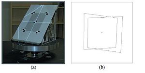
Figure 1: Diagram and image of a spinning mirror system. The diagram shows the mirror system and the synchronized engine that displays light from the high speed video projector.
Spinning mirror systems are used to build interactive 3D graphics and autostereoscopic visuals visible to multiple simultaneous viewers, since a different view can be perceived by each viewer depending on the angle of vision.
Because these mirrors spin, they can reflect light from a projector to any outside point. Therefore, such systems can create omnidirectional projections. Because light is reflected directly from the projector to the audience and not projected onto a fixed plane, spinning mirror systems create a correct interpretation of the field of light regardless of a spectator's position relative to the system.
Because such systems are tied to a high speed video projector, the system's maximum resolution of unique angles is limited by the projector's maximum framerate.
A similar system was commercially released in 1981 for the Entex Adventure Vision game console. The console, however, didn't aim for 3D visualization, but instead used the spinning mirror to project a 2D picture from a row of LEDs.
Motivation
Previous volumetric systems projected the images in a diffuse plane of rotation, thus, the light was remaining dispersed in all directions. Unfortunately, these displays could not recreate dependent effects such as occlusion. This produced the need to create a system that was capable of settling misadventures as this one, but in turn, it had an easy implementation and was doing that his installation on systems was simple. Thus, create a system of gyratory mirrors covered by a holographic diffuser anisotropic.
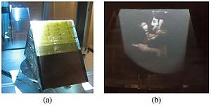
Figure 2:anisotropic reflectance characteristics of the mirror system. Left: Photographs of a laser beam and a thin vertical line of light from the video projector as reflected by the holographic diffuser and mirror toward the viewer. The horizontal width represented in each image is four degrees. The bottom image shows the ideal bilinear interpolation spread of a hat function whose radius matches the 1.25° angular separation of the display's successive views. Right: Graphs of the horizontal intensity profiles of the images at left. Dotted red is the laser, solid blue is the projector, and dashed black is the bilinear interpolation function.
Functioning
The mirrored surface reflects each projector pixel to a narrow range of viewpoints. The holographic diffuser provides control over the width and height of this region. The characteristics of the diffuser are such that the relative diffusion between x and y is approximately 1:200.
Horizontally, the surface is sharply specular to maintain a 1.25-degree separation between views. Vertically, the mirror scatters widely so the projected image can be viewed from essentially any height.
The horizontal profile of the specular lobe approximates a bilinear interpolation between adjacent viewpoints; the motion of the mirror adds some additional blur which improves the reproduction of halftoned imagery at the expense of angular resolution.
Montage
The anisotropic holographic diffuser and mirror assembly are mounted on a carbon fiber panel and attached to an aluminum flywheel at 45°. The flywheel spins synchronously relative to the images displayed by the projector.
Figure 3: (a)Fiducial markers used for determining the projection matrix P. (b) The four outer mirror fiducials as seen by the projector with the mirror at 0° and 180°
Synchronization in a system
Because the output frame rate of the PC graphics card is relatively constant and cannot be fine-tuned on the fly, The PC video output rate is used as the master signal for system synchronization. The projector's FPGA also creates signals encoding the current frame rate. These control signals interface directly to an Animatics SM3420D ”Smart Motor" which contains firmware and motion control parameters resulting in a stable, velocity-based control loop that ensures the motor velocity stays in sync with the signals from the projector.
Projection of graphs on the screen
Figure 4: (a) Intersection of a vertically diffused ray of light with the circular locus of viewpoints V. (b) Seen from above, rays leaving the mirror diverge from the projector's reflected nodal point to multiple viewpoints. The viewpoint corresponding to vertex Q is found by intersecting the vertical plane containing ray PQ with the viewing circle V. (c) When preprocessing a light field, the intersection point V0 determines the nearest horizontal views to sample.
In this section we describe how to render a scene to the 3D display with correct perspective, using either scanline rendering or ray tracing. We assume that the spinning mirror is centered at the origin and that its axis of rotation is the vertical y-axis, with the video projector at the nodal point P above the mirror as in top figure. We further assume that the viewpoint for which the correct perspective should be obtained is at a height h and a distance d from the y axis.
By the rotational symmetry of our system, we can produce perspective-correct imagery for any viewing position on the circle V defined by h and d, yielding binocular images for a viewer facing the display since h and d will be similar for both eyes. We denote a particular viewpoint on the circle V as V'. In practice, the set of perspective-correct viewpoints V need not be a continuous planar circle and can pass through a variety of tracked viewer positions at different distances and heights.
Double spinning mirror system
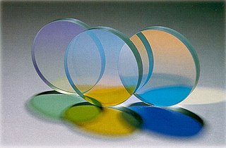
Figure 5: a) two mirrors to show the images in color using cyan filters and orange under the diffusers. b) A color photography of the images that are obtained by this system.
In advance of that, we have implemented a two-channel field-sequential color system using a two-sided tent-shaped diffusing mirror. For each side of the tent, we place a color filter between the holographic diffusing film and the first-surface mirror, which avoids introducing specular first-surface reflections. We chose a cyan filter for one side and an orange filter for the other, dividing the visible spectrum approximately evenly into short and long wavelengths.
We convert RGB colors to Orange-Cyan colors by projecting the linear RGB vector onto the plane spanned by the Orange and Cyan colors.
To render in color, we calibrate each plane of the tent mirror independently as in Section 5. Then, we render the 3D scene twice for each sub-frame, once for the orange side and once for the cyan side, and the calibration process ensures that each side is rendered toward the appropriate set of viewpoints. The effect for the viewer is similar to the Kinemacolor, 2-color cinema system and the choice of filters allows for useful color reproduction for many scenes.
Applications
System Maeda [Maeda, 2003]: it is based on a system of a monitor of gyratory LCD. The weight of this monitor limits the rate of update, allowing only five revolutions per second, obtaining only five independent points of view.
System Transport [Otsuka, 2006]: it realizes 24 images in the foreign edge of the projected video and reflects these images on a screen anisotropic of rapid rotation using a circle created by different faces of mirrors.
3D Videoconference [California, 2009]: It is based on a structure composed of two mirrors on those who reflect the images and create different perspectives about his 360 degrees.
Articles and books
TRAVIS, A. R. L. 1997. The display of three-dimensional video images.
ENDO, T., KAJIKI, Y., HONDA, T., AND SATO, M. 2000. Cylindrical 3D video display observable from all directions.
DODGSON, N. A. 2005. Autostereoscopic 3D displays.
MCDOWALL, I., AND BOLAS, M. 2005. Display, sensing, and control applications for digital micromirror displays.
FAVALORA, G. E. 2005. Volumetric 3D displays and application infrastructure.
OTSUKA, R., HOSHINO, T., AND HORRY, Y. 2006. Transpost: A novel approach to the display and transmission of 360 degreesviewable 3D solid images.
AGOCS, T., BALOGH, T., FORGACS, T., BETTIO, F., GOBBETTI, E., ZANETTI, G., AND BOUVIER, E. 2006. A large scale interactive holographic display.
External links
• Video depicting a spinning mirror system
•Archived 27 October 2009 at the Wayback Machine Type of Display obtained thanks to the described technology
• Article about the use of the system in 3D Teleconferencing
• Paper about spinning mirror systems
Related Research Articles
Texture mapping is a method for mapping a texture on a computer-generated graphic. Texture here can be high frequency detail, surface texture, or color.
The Phong reflection model is an empirical model of the local illumination of points on a surface designed by the computer graphics researcher Bui Tuong Phong. In 3D computer graphics, it is sometimes referred to as "Phong shading", particularly if the model is used with the interpolation method of the same name and in the context of pixel shaders or other places where a lighting calculation can be referred to as “shading”.
Stereoscopy is a technique for creating or enhancing the illusion of depth in an image by means of stereopsis for binocular vision. The word stereoscopy derives from Greek στερεός (stereos) 'firm, solid', and σκοπέω (skopeō) 'to look, to see'. Any stereoscopic image is called a stereogram. Originally, stereogram referred to a pair of stereo images which could be viewed using a stereoscope.
In color reproduction, including computer graphics and photography, the gamut, or color gamut, is a certain complete subset of colors. The most common usage refers to the subset of colors that can be accurately represented in a given circumstance, such as within a given color space or by a certain output device.
Digital Light Processing (DLP) is a set of chipsets based on optical micro-electro-mechanical technology that uses a digital micromirror device. It was originally developed in 1987 by Larry Hornbeck of Texas Instruments. While the DLP imaging device was invented by Texas Instruments, the first DLP-based projector was introduced by Digital Projection Ltd in 1997. Digital Projection and Texas Instruments were both awarded Emmy Awards in 1998 for the DLP projector technology. DLP is used in a variety of display applications from traditional static displays to interactive displays and also non-traditional embedded applications including medical, security, and industrial uses.
A 3D display is a display device capable of conveying depth to the viewer. Many 3D displays are stereoscopic displays, which produce a basic 3D effect by means of stereopsis, but can cause eye strain and visual fatigue. Newer 3D displays such as holographic and light field displays produce a more realistic 3D effect by combining stereopsis and accurate focal length for the displayed content. Newer 3D displays in this manner cause less visual fatigue than classical stereoscopic displays.
A volumetric display device is a display device that forms a visual representation of an object in three physical dimensions, as opposed to the planar image of traditional screens that simulate depth through a number of different visual effects. One definition offered by pioneers in the field is that volumetric displays create 3D imagery via the emission, scattering, or relaying of illumination from well-defined regions in (x,y,z) space.
A dichroic filter, thin-film filter, or interference filter is a color filter used to selectively pass light of a small range of colors while reflecting other colors. By comparison, dichroic mirrors and dichroic reflectors tend to be characterized by the colors of light that they reflect, rather than the colors they pass.
A specular highlight is the bright spot of light that appears on shiny objects when illuminated. Specular highlights are important in 3D computer graphics, as they provide a strong visual cue for the shape of an object and its location with respect to light sources in the scene.
A polarized 3D system uses polarization glasses to create the illusion of three-dimensional images by restricting the light that reaches each eye.
Anaglyph 3D is the stereoscopic 3D effect achieved by means of encoding each eye's image using filters of different colors, typically red and cyan. Anaglyph 3D images contain two differently filtered colored images, one for each eye. When viewed through the "color-coded" "anaglyph glasses", each of the two images reaches the eye it's intended for, revealing an integrated stereoscopic image. The visual cortex of the brain fuses this into the perception of a three-dimensional scene or composition.
A projection screen is an installation consisting of a surface and a support structure used for displaying a projected image for the view of an audience. Projection screens may be permanently installed on a wall, as in a movie theater, mounted to or placed in a ceiling using a rollable projection surface that retracts into a casing, painted on a wall, or portable with tripod or floor rising models as in a conference room or other non-dedicated viewing space. Another popular type of portable screens are inflatable screens for outdoor movie screening.
Autostereoscopy is any method of displaying stereoscopic images without the use of special headgear, glasses, something that affects vision, or anything for eyes on the part of the viewer. Because headgear is not required, it is also called "glasses-free 3D" or "glassesless 3D". There are two broad approaches currently used to accommodate motion parallax and wider viewing angles: eye-tracking, and multiple views so that the display does not need to sense where the viewer's eyes are located. Examples of autostereoscopic displays technology include lenticular lens, parallax barrier, and may include Integral imaging, but notably do not include volumetric display or holographic displays.
The Blinn–Phong reflection model, also called the modified Phong reflection model, is a modification developed by Jim Blinn to the Phong reflection model.
Computer graphics lighting is the collection of techniques used to simulate light in computer graphics scenes. While lighting techniques offer flexibility in the level of detail and functionality available, they also operate at different levels of computational demand and complexity. Graphics artists can choose from a variety of light sources, models, shading techniques, and effects to suit the needs of each application.
Phantograms, also known as Phantaglyphs, Op-Ups, free-standing anaglyphs, levitated images, and book anaglyphs, are a form of optical illusion. Phantograms use perspectival anamorphosis to produce a 2D image that is distorted in a particular way so as to appear, to a viewer at a particular vantage point, three-dimensional, standing above or recessed into a flat surface. The illusion of depth and perspective is heightened by stereoscopy techniques; a combination of two images, most typically but not necessarily an anaglyph. With common (red–cyan) 3D glasses, the viewer's vision is segregated so that each eye sees a different image.
Large-screen television technology developed rapidly in the late 1990s and 2000s. Prior to the development of thin-screen technologies, rear-projection television was standard for larger displays, and jumbotron, a non-projection video display technology, was used at stadiums and concerts. Various thin-screen technologies are being developed, but only liquid crystal display (LCD), plasma display (PDP) and Digital Light Processing (DLP) have been publicly released. Recent technologies like organic light-emitting diode (OLED) as well as not-yet-released technologies like surface-conduction electron-emitter display (SED) or field emission display (FED) are in development to replace earlier flat-screen technologies in picture quality.
Zebra Imaging was a company that developed 3D digital holographic images, hologram imagers and interactive 3D displays for government and commercial uses. The company offers digital holograms that are autostereoscopic, full-parallax and in monochrome or full-color. They have also developed a 3D Dynamic Display, which is capable of rendering holograms in real time; design work with 3D programs such as SketchUp and 123D Catch can be viewed on a holographic display while they are actively being edited.
Specular holography is a technique for making three dimensional imagery by controlling the motion of specular glints on a two-dimensional surface. The image is made of many specularities and has the appearance of a 3D surface-stippling made of dots of light. Unlike conventional wavefront holograms, specular holograms do not depend on wave optics, photographic media, or lasers.
This is a glossary of terms relating to computer graphics.
This page is based on this Wikipedia article Text is available under the CC BY-SA 4.0 license; additional terms may apply. Images, videos and audio are available under their respective licenses.