Related Research Articles
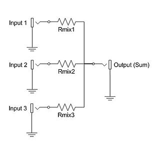
An electronic mixer is a device that combines two or more electrical or electronic signals into one or two composite output signals. There are two basic circuits that both use the term mixer, but they are very different types of circuits: additive mixers and multiplicative mixers. Additive mixers are also known as "analog adders" to distinguish from the related digital adder circuits.

An amplifier, electronic amplifier or (informally) amp is an electronic device that can increase the power of a signal. It is a two-port electronic circuit that uses electric power from a power supply to increase the amplitude of a signal applied to its input terminals, producing a proportionally greater amplitude signal at its output. The amount of amplification provided by an amplifier is measured by its gain: the ratio of output voltage, current, or power to input. An amplifier is a circuit that has a power gain greater than one.

In electronics, an analog-to-digital converter is a system that converts an analog signal, such as a sound picked up by a microphone or light entering a digital camera, into a digital signal. An ADC may also provide an isolated measurement such as an electronic device that converts an input analog voltage or current to a digital number representing the magnitude of the voltage or current. Typically the digital output is a two's complement binary number that is proportional to the input, but there are other possibilities.

In electronics, a comparator is a device that compares two voltages or currents and outputs a digital signal indicating which is larger. It has two analog input terminals and and one binary digital output . The output is ideally

A phase-locked loop or phase lock loop (PLL) is a control system that generates an output signal whose phase is related to the phase of an input signal. There are several different types; the simplest is an electronic circuit consisting of a variable frequency oscillator and a phase detector in a feedback loop. The oscillator generates a periodic signal, and the phase detector compares the phase of that signal with the phase of the input periodic signal, adjusting the oscillator to keep the phases matched.
Demodulation is extracting the original information-bearing signal from a carrier wave. A demodulator is an electronic circuit that is used to recover the information content from the modulated carrier wave. There are many types of modulation so there are many types of demodulators. The signal output from a demodulator may represent sound, images or binary data.

Automatic gain control (AGC), is a closed-loop feedback regulating circuit in an amplifier or chain of amplifiers, the purpose of which is to maintain a suitable signal amplitude at its output, despite variation of the signal amplitude at the input. The average or peak output signal level is used to dynamically adjust the gain of the amplifiers, enabling the circuit to work satisfactorily with a greater range of input signal levels. It is used in most radio receivers to equalize the average volume (loudness) of different radio stations due to differences in received signal strength, as well as variations in a single station's radio signal due to fading. Without AGC the sound emitted from an AM radio receiver would vary to an extreme extent from a weak to a strong signal; the AGC effectively reduces the volume if the signal is strong and raises it when it is weaker. In a typical receiver the AGC feedback control signal is usually taken from the detector stage and applied to control the gain of the IF or RF amplifier stages.

An envelope detector is an electronic circuit that takes a (relatively) high-frequency amplitude modulated signal as input and provides an output which is the envelope of the original signal.
A phase detector or phase comparator is a frequency mixer, analog multiplier or logic circuit that generates a voltage signal which represents the difference in phase between two signal inputs. It is an essential element of the phase-locked loop (PLL).

In electronics, a mixer, or frequency mixer, is a nonlinear electrical circuit that creates new frequencies from two signals applied to it. In its most common application, two signals are applied to a mixer, and it produces new signals at the sum and difference of the original frequencies. Other frequency components may also be produced in a practical frequency mixer.
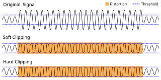
In electronics, a limiter is a circuit that allows signals below a specified input power or level to pass unaffected while attenuating (lowering) the peaks of stronger signals that exceed this threshold. Limiting is a type of dynamic range compression. Clipping is an extreme version of limiting.
The Foster–Seeley discriminator is a common type of FM detector circuit, invented in 1936 by Dudley E. Foster and Stuart William Seeley. The circuit was envisioned for automatic frequency control of receivers, but also found application in demodulating an FM signal. It uses a tuned RF transformer to convert frequency changes into amplitude changes. A transformer, tuned to the carrier frequency, is connected to two rectifier diodes. The circuit resembles a full-wave bridge rectifier. If the input equals the carrier frequency, the two halves of the tuned transformer circuit produce the same rectified voltage and the output is zero. As the frequency of the input changes, the balance between the two halves of the transformer secondary changes, and the result is a voltage proportional to the frequency deviation of the carrier.
Linear electronic oscillator circuits, which generate a sinusoidal output signal, are composed of an amplifier and a frequency selective element, a filter. A linear oscillator circuit which uses an RC network, a combination of resistors and capacitors, for its frequency selective part is called an RC oscillator.
In physics, quantum noise refers to the uncertainty of a physical quantity that is due to its quantum origin. In certain situations, quantum noise appears as shot noise; for example, most optical communications use amplitude modulation, and thus, the quantum noise appears as shot noise only. For the case of uncertainty in the electric field in some lasers, the quantum noise is not just shot noise; uncertainties of both amplitude and phase contribute to the quantum noise. This issue becomes important in the case of noise of a quantum amplifier, which preserves the phase. The phase noise becomes important when the energy of the frequency modulation or phase modulation of waves is comparable to the energy of the signal.

In radio, a detector is a device or circuit that extracts information from a modulated radio frequency current or voltage. The term dates from the first three decades of radio (1888-1918). Unlike modern radio stations which transmit sound on an uninterrupted carrier wave, early radio stations transmitted information by radiotelegraphy. The transmitter was switched on and off to produce long or short periods of radio waves, spelling out text messages in Morse code. Therefore, early radio receivers had only to distinguish between the presence or absence of a radio signal. The device that performed this function in the receiver circuit was called a detector. A variety of different detector devices, such as the coherer, electrolytic detector, magnetic detector and the crystal detector, were used during the wireless telegraphy era until superseded by vacuum tube technology.
In electronics, a differentiator is a circuit that is designed such that the output of the circuit is approximately directly proportional to the rate of change of the input. A true differentiator cannot be physically realized, because it has infinite gain at infinite frequency. A similar effect can be achieved, however, by limiting the gain above some frequency. The differentiator circuit is essentially a high-pass filter.
An active differentiator includes some form of amplifier, while a passive differentiator is made only of resistors, capacitors and inductors.

The autodyne circuit was an improvement to radio signal amplification using the De Forest Audion vacuum tube amplifier. By allowing the tube to oscillate at a frequency slightly different from the desired signal, the sensitivity over other receivers was greatly improved. The autodyne circuit was invented by Edwin Howard Armstrong of Columbia University, New York, NY. He inserted a tuned circuit in the output circuit of the Audion vacuum tube amplifier. By adjusting the tuning of this tuned circuit, Armstrong was able to dramatically increase the gain of the Audion amplifier. Further increase in tuning resulted in the Audion amplifier reaching self-oscillation.
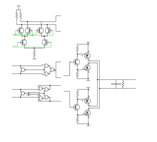
In electronics, the Gilbert cell is a type of mixer. It produces output signals that are proportional to the product of two input signals. Such circuits are widely used for frequency conversion in radio systems. The advantage of this circuit is the output current is an accurate multiplication of the (differential) base currents of both inputs. As a mixer, its balanced operation cancels out many unwanted mixing products, resulting in a "cleaner" output.
Optical heterodyne detection is a method of extracting information encoded as modulation of the phase, frequency or both of electromagnetic radiation in the wavelength band of visible or infrared light. The light signal is compared with standard or reference light from a "local oscillator" (LO) that would have a fixed offset in frequency and phase from the signal if the latter carried null information. "Heterodyne" signifies more than one frequency, in contrast to the single frequency employed in homodyne detection.
Power amplifier classes are, in electronics, letter symbols applied to different power amplifier types. The class gives a broad indication of an amplifer's characteristics and performance. The classes are related to the time period that the active amplifier device is passing current, expressed as a fraction of the period of a signal waveform applied to the input. A class A amplifier is conducting through all the period of the signal; Class B only for one-half the input period, class C for much less than half the input period. A Class D amplifier operates its output device in a switching manner; the fraction of the time that the device is conducting is adjusted so a pulse width modulation output is obtained from the stage.
References
- ↑ IEEE Std. 100 Authoritative Dictionary of Standards Terms Seventh Edition, IEEE, 2000, ISBN 0738126012,Square law detection
- ↑ H. C. Torrey, C. A. Whitmer, Crystal Rectifiers, New York: McGraw-Hill, 1948, pp. 3 - 4
| This signal processing-related article is a stub. You can help Wikipedia by expanding it. |