
Microwave is a form of electromagnetic radiation with wavelengths ranging from about one meter to one millimeter; with frequencies between 300 MHz (1 m) and 300 GHz (1 mm). Different sources define different frequency ranges as microwaves; the above broad definition includes both UHF and EHF bands. A more common definition in radio-frequency engineering is the range between 1 and 100 GHz. In all cases, microwaves include the entire SHF band at minimum. Frequencies in the microwave range are often referred to by their IEEE radar band designations: S, C, X, Ku, K, or Ka band, or by similar NATO or EU designations.

Radar is a detection system that uses radio waves to determine the range, angle, or velocity of objects. It can be used to detect aircraft, ships, spacecraft, guided missiles, motor vehicles, weather formations, and terrain. A radar system consists of a transmitter producing electromagnetic waves in the radio or microwaves domain, a transmitting antenna, a receiving antenna and a receiver and processor to determine properties of the object(s). Radio waves from the transmitter reflect off the object and return to the receiver, giving information about the object's location and speed.

In antenna theory, a phased array usually means an electronically scanned array, a computer-controlled array of antennas which creates a beam of radio waves that can be electronically steered to point in different directions without moving the antennas.

In telecommunications and radar, a reflective array antenna is a class of directive antennas in which multiple driven elements are mounted in front of a flat surface designed to reflect the radio waves in a desired direction. They are a type of array antenna. They are often used in the VHF and UHF frequency bands. VHF examples are generally large and resemble a highway billboard, so they are sometimes called billboard antennas, or in Britain hoarding antennas. Other names are bedspring array and bowtie array depending on the type of elements making up the antenna. The curtain array is a larger version used by shortwave radio broadcasting stations.

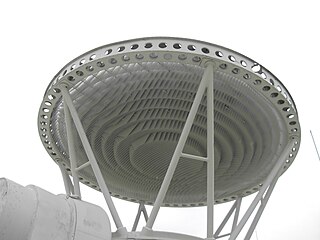
A parabolic antenna is an antenna that uses a parabolic reflector, a curved surface with the cross-sectional shape of a parabola, to direct the radio waves. The most common form is shaped like a dish and is popularly called a dish antenna or parabolic dish. The main advantage of a parabolic antenna is that it has high directivity. It functions similarly to a searchlight or flashlight reflector to direct the radio waves in a narrow beam, or receive radio waves from one particular direction only. Parabolic antennas have some of the highest gains, meaning that they can produce the narrowest beamwidths, of any antenna type. In order to achieve narrow beamwidths, the parabolic reflector must be much larger than the wavelength of the radio waves used, so parabolic antennas are used in the high frequency part of the radio spectrum, at UHF and microwave (SHF) frequencies, at which the wavelengths are small enough that conveniently-sized reflectors can be used.
Super high frequency (SHF) is the ITU designation for radio frequencies (RF) in the range between 3 and 30 gigahertz (GHz). This band of frequencies is also known as the centimetre band or centimetre wave as the wavelengths range from one to ten centimetres. These frequencies fall within the microwave band, so radio waves with these frequencies are called microwaves. The small wavelength of microwaves allows them to be directed in narrow beams by aperture antennas such as parabolic dishes and horn antennas, so they are used for point-to-point communication and data links and for radar. This frequency range is used for most radar transmitters, wireless LANs, satellite communication, microwave radio relay links, and numerous short range terrestrial data links. They are also used for heating in industrial microwave heating, medical diathermy, microwave hyperthermy to treat cancer, and to cook food in microwave ovens.

A horn antenna or microwave horn is an antenna that consists of a flaring metal waveguide shaped like a horn to direct radio waves in a beam. Horns are widely used as antennas at UHF and microwave frequencies, above 300 MHz. They are used as feed antennas for larger antenna structures such as parabolic antennas, as standard calibration antennas to measure the gain of other antennas, and as directive antennas for such devices as radar guns, automatic door openers, and microwave radiometers. Their advantages are moderate directivity, low standing wave ratio (SWR), broad bandwidth, and simple construction and adjustment.

A slot antenna consists of a metal surface, usually a flat plate, with one or more holes or slots cut out. When the plate is driven as an antenna by an applied radio frequency current, the slot radiates electromagnetic waves in a way similar to a dipole antenna. The shape and size of the slot, as well as the driving frequency, determine the radiation pattern. Slot antennas are usually used at UHF and microwave frequencies at which wavelengths are small enough that the plate and slot are conveniently small. At these frequencies, the radio waves are often conducted by a waveguide, and the antenna consists of slots in the waveguide; this is called a slotted waveguide antenna. Multiple slots act as a directive array antenna and can emit a narrow fan-shaped beam of microwaves. They are used in standard laboratory microwave sources used for research, UHF television transmitting antennas, antennas on missiles and aircraft, sector antennas for cellular base stations, and particularly marine radar antennas. A slot antenna's main advantages are its size, design simplicity, and convenient adaptation to mass production using either waveguide or PC board technology.

An antenna reflector is a device that reflects electromagnetic waves. Antenna reflectors can exist as a standalone device for redirecting radio frequency (RF) energy, or can be integrated as part of an antenna assembly.
Monopulse radar is a radar system that uses additional encoding of the radio signal to provide accurate directional information. The name refers to its ability to extract range and direction from a single signal pulse.
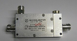
Power dividers and directional couplers are passive devices used mostly in the field of radio technology. They couple a defined amount of the electromagnetic power in a transmission line to a port enabling the signal to be used in another circuit. An essential feature of directional couplers is that they only couple power flowing in one direction. Power entering the output port is coupled to the isolated port but not to the coupled port. A directional coupler designed to split power equally between two ports is called a hybrid coupler.
Radar engineering details are technical details pertaining to the components of a radar and their ability to detect the return energy from moving scatterers — determining an object's position or obstruction in the environment. This includes field of view in terms of solid angle and maximum unambiguous range and velocity, as well as angular, range and velocity resolution. Radar sensors are classified by application, architecture, radar mode, platform, and propagation window.

A phase shift module is a microwave network module which provides a controllable phase shift of the RF signal. Phase shifters are used in phased arrays.
Leaky-Wave Antenna (LWA) belong to the more general class of Traveling wave antenna, that use a traveling wave on a guiding structure as the main radiating mechanism. Traveling-wave antenna fall into two general categories, slow-wave antennas and fast-wave antennas, which are usually referred to as leaky-wave antennas.
A lens antenna is a microwave antenna that uses a shaped piece of microwave-transparent material to bend and focus the radio waves by refraction, as an optical lens does for light. Typically it consists of a small feed antenna such as a patch antenna or horn antenna which radiates radio waves, with a piece of dielectric or composite material in front which functions as a converging lens to collimate the radio waves into a beam. Conversely, in a receiving antenna the lens focuses the incoming radio waves onto the feed antenna, which converts them to electric currents which are delivered to a radio receiver. They can also be fed by an array of feed antennas, called a focal plane array (FPA), to create more complicated radiation patterns.
In radio systems, many different antenna types are used with specialized properties for particular applications. Antennas can be classified in various ways. The list below groups together antennas under common operating principles, following the way antennas are classified in many engineering textbooks.
A Butler matrix is a beamforming network used to feed a phased array of antenna elements. Its purpose is to control the direction of a beam, or beams, of radio transmission. It consists of an matrix of hybrid couplers and fixed-value phase shifters where is some power of 2. The device has input ports to which power is applied, and output ports to which antenna elements are connected. The Butler matrix feeds power to the elements with a progressive phase difference between elements such that the beam of radio transmission is in the desired direction. The beam direction is controlled by switching power to the desired beam port. More than one beam, or even all of them can be activated simultaneously.
Martello is a family of phased array radar systems developed by Marconi Electronic Systems in the 1970s and introduced operationally in the early 1980s. They provided long-range early warning capabilities but also had the accuracy needed for interception plotting and "putting on" of other weapons systems like surface-to-air missiles. The name comes from the Martello towers that provided defence in earlier years.
The AR-3D was a military air traffic control and early warning radar developed by Plessey and first produced in 1975. It used a pencil beam and simple frequency scanning system known as "squint scan" to produce a low-cost 3D radar system that was also relatively mobile. About 23 were produced in total and found sales around the world into the early 1980s.
The AR-320 is a 3D early warning radar developed by the UK's Plessey in partnership with US-based ITT-Gilfillan. The system combined the receiver electronics, computer systems and displays of the earlier Plessey AR-3D with a Gilfillan-developed transmitter and planar array antenna from their S320 series. The main advantage over the AR-3D was the ability to shift frequencies to provide a level of frequency agility and thus improve its resistance to jamming.
