In digital logic and computing, a counter is a device which stores the number of times a particular event or process has occurred, often in relationship to a clock. The most common type is a sequential digital logic circuit with an input line called the clock and multiple output lines. The values on the output lines represent a number in the binary or BCD number system. Each pulse applied to the clock input increments or decrements the number in the counter.

Feedback occurs when outputs of a system are routed back as inputs as part of a chain of cause-and-effect that forms a circuit or loop. The system can then be said to feed back into itself. The notion of cause-and-effect has to be handled carefully when applied to feedback systems:
Simple causal reasoning about a feedback system is difficult because the first system influences the second and second system influences the first, leading to a circular argument. This makes reasoning based upon cause and effect tricky, and it is necessary to analyze the system as a whole. As provided by Webster, feedback in business is the transmission of evaluative or corrective information about an action, event, or process to the original or controlling source.

In telecommunications, RS-232 or Recommended Standard 232 is a standard originally introduced in 1960 for serial communication transmission of data. It formally defines signals connecting between a DTE such as a computer terminal or PC, and a DCE, such as a modem. The standard defines the electrical characteristics and timing of signals, the meaning of signals, and the physical size and pinout of connectors. The current version of the standard is TIA-232-F Interface Between Data Terminal Equipment and Data Circuit-Terminating Equipment Employing Serial Binary Data Interchange, issued in 1997. The RS-232 standard had been commonly used in computer serial ports and is still widely used in industrial communication devices.

Digital electronics is a field of electronics involving the study of digital signals and the engineering of devices that use or produce them. This is in contrast to analog electronics which work primarily with analog signals. Despite the name, digital electronics designs includes important analog design considerations.
In electronics and telecommunications, jitter is the deviation from true periodicity of a presumably periodic signal, often in relation to a reference clock signal. In clock recovery applications it is called timing jitter. Jitter is a significant, and usually undesired, factor in the design of almost all communications links.
A phase-locked loop or phase lock loop (PLL) is a control system that generates an output signal whose phase is fixed relative to the phase of an input signal. Keeping the input and output phase in lockstep also implies keeping the input and output frequencies the same, thus a phase-locked loop can also track an input frequency. And by incorporating a frequency divider, a PLL can generate a stable frequency that is a multiple of the input frequency.
In automata theory, sequential logic is a type of logic circuit whose output depends on the present value of its input signals and on the sequence of past inputs, the input history. This is in contrast to combinational logic, whose output is a function of only the present input. That is, sequential logic has state (memory) while combinational logic does not.

In electronics and especially synchronous digital circuits, a clock signal is an electronic logic signal which oscillates between a high and a low state at a constant frequency and is used like a metronome to synchronize actions of digital circuits. In a synchronous logic circuit, the most common type of digital circuit, the clock signal is applied to all storage devices, flip-flops and latches, and causes them all to change state simultaneously, preventing race conditions.
Delay-line memory is a form of computer memory, mostly obsolete, that was used on some of the earliest digital computers, and is reappearing in the form of optical delay lines. Like many modern forms of electronic computer memory, delay-line memory was a refreshable memory, but as opposed to modern random-access memory, delay-line memory was sequential-access.

A real-time clock (RTC) is an electronic device that measures the passage of time.
Clock skew is a phenomenon in synchronous digital circuit systems in which the same sourced clock signal arrives at different components at different times due to gate or, in more advanced semiconductor technology, wire signal propagation delay. The instantaneous difference between the readings of any two clocks is called their skew.

In electronics, metastability is the ability of a digital electronic system to persist for an unbounded time in an unstable equilibrium or metastable state. In digital logic circuits, a digital signal is required to be within certain voltage or current limits to represent a '0' or '1' logic level for correct circuit operation; if the signal is within a forbidden intermediate range it may cause faulty behavior in logic gates the signal is applied to. In metastable states, the circuit may be unable to settle into a stable '0' or '1' logic level within the time required for proper circuit operation. As a result, the circuit can act in unpredictable ways, and may lead to a system failure, sometimes referred to as a "glitch". Metastability is an instance of the Buridan's ass paradox.
Static timing analysis (STA) is a simulation method of computing the expected timing of a synchronous digital circuit without requiring a simulation of the full circuit.
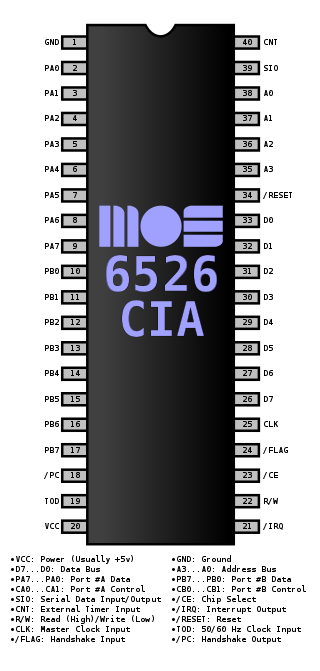
The 6526/8520 Complex Interface Adapter (CIA) was an integrated circuit made by MOS Technology. It served as an I/O port controller for the 6502 family of microprocessors, providing for parallel and serial I/O capabilities as well as timers and a Time-of-Day (TOD) clock. The device's most prominent use was in the Commodore 64 and Commodore 128(D), each of which included two CIA chips. The Commodore 1570 and Commodore 1571 floppy disk drives contained one CIA each. Furthermore, the Amiga home computers and the Commodore 1581 floppy disk drive employed a modified variant of the CIA circuit called 8520. 8520 is functionally equivalent to the 6526 except for the simplified TOD circuitry. Predecessor to CIA was PIA.

Signal integrity or SI is a set of measures of the quality of an electrical signal. In digital electronics, a stream of binary values is represented by a voltage waveform. However, digital signals are fundamentally analog in nature, and all signals are subject to effects such as noise, distortion, and loss. Over short distances and at low bit rates, a simple conductor can transmit this with sufficient fidelity. At high bit rates and over longer distances or through various mediums, various effects can degrade the electrical signal to the point where errors occur and the system or device fails. Signal integrity engineering is the task of analyzing and mitigating these effects. It is an important activity at all levels of electronics packaging and assembly, from internal connections of an integrated circuit (IC), through the package, the printed circuit board (PCB), the backplane, and inter-system connections. While there are some common themes at these various levels, there are also practical considerations, in particular the interconnect flight time versus the bit period, that cause substantial differences in the approach to signal integrity for on-chip connections versus chip-to-chip connections.
The primary focus of this article is asynchronous control in digital electronic systems. In a synchronous system, operations are coordinated by one, or more, centralized clock signals. An asynchronous system, in contrast, has no global clock. Asynchronous systems do not depend on strict arrival times of signals or messages for reliable operation. Coordination is achieved using event-driven architecture triggered by network packet arrival, changes (transitions) of signals, handshake protocols, and other methods.
In digital electronic design a clock domain crossing (CDC), or simply clock crossing, is the traversal of a signal in a synchronous digital circuit from one clock domain into another. If a signal does not assert long enough and is not registered, it may appear asynchronous on the incoming clock boundary.
Globally asynchronous locally synchronous (GALS), in electronics, is an architecture for designing electronic circuits that addresses the problem of safe and reliable data transfer between independent clock domains. GALS is a model of computation that emerged in the 1980s. It allows to design computer systems consisting of several synchronous islands interacting with other islands using asynchronous communication, e.g. with FIFOs.
A digital signal is a signal that represents data as a sequence of discrete values; at any given time it can only take on, at most, one of a finite number of values. This contrasts with an analog signal, which represents continuous values; at any given time it represents a real number within a continuous range of values.

In electronics, flip-flops and latches are circuits that have two stable states that can store state information – a bistable multivibrator. The circuit can be made to change state by signals applied to one or more control inputs and will output its state. It is the basic storage element in sequential logic. Flip-flops and latches are fundamental building blocks of digital electronics systems used in computers, communications, and many other types of systems.
