Transponder landing system

Last updated
TLS electronics shelter, elevation sensor and uplink antennas - Santa Cruz Air Force Base, Rio de Janeiro, Brazil, August 2009 BASC TLS.jpg
TLS electronics shelter, elevation sensor and uplink antennas – Santa Cruz Air Force Base, Rio de Janeiro, Brazil, August 2009
TLS at Teniente Rodolfo Marsh Martin Aerodrome November 2010, Base Presidente Eduardo Frei Montalva Antarctica TLS installed at SCRM Antarctica.jpg
TLS at Teniente Rodolfo Marsh Martin Aerodrome November 2010, Base Presidente Eduardo Frei Montalva Antarctica

A transponder landing system (TLS) is an all-weather, precision landing system that uses existing airborne transponder and instrument landing system (ILS) equipment to create a precision approach at a location where an ILS would normally not be available.

Contents

Description

Aircraft position tracks over southern Spain as determined by TLS TLS GCA console surveillance.JPG
Aircraft position tracks over southern Spain as determined by TLS
PAR Format: All aircraft positions within the display field of view are depicted TLS PAR console all in view.JPG
PAR Format: All aircraft positions within the display field of view are depicted
PAR format: Single aircraft may be selected for each of the operator consoles to provide talk-down guidance TLS PAR console approach.JPG
PAR format: Single aircraft may be selected for each of the operator consoles to provide talk-down guidance
Transportable TLS (TTLS) owned by the Spanish Air Force deployed at an undisclosed location in 2010 Transportable TLS.jpg
Transportable TLS (TTLS) owned by the Spanish Air Force deployed at an undisclosed location in 2010
US Air Force Transportable TLS (TTLS) deployed at an undisclosed location in 2010 TTLS 2009 undisclosed USAF location.JPG
US Air Force Transportable TLS (TTLS) deployed at an undisclosed location in 2010

Conventional ILS systems broadcast using a number of "single purpose" antennas. The localizer array consists of 8 to 14 or more antenna elements and is typically located 2000+ feet from the runway approach threshold, which is often beyond the departure end of the runway and provides a fan-shaped signal for azimuth direction (side to side). The other antenna array is located beside the runway and provides elevation to indicate a standard glideslope. This complex set of antennas is expensive to install and maintain and is often difficult to site in areas with uneven terrain or obstacles that could interfere with its guidance signals.

Function

The TLS facility interrogates the transponders of all aircraft within 100 nautical miles (190 km). After receiving a response, TLS determines the aircraft's location using three sets of antenna arrays: one for horizontal position using monopulse techniques, the other for vertical monopulse [1] and a third for trilateration. TLS then calculates the position of all aircraft using the transponder replies and converts that into real-time guidance for an aircraft cleared for approach based on its position relative to the desired approach path. The position tracks for all aircraft in the TLS service volume are displayed on an ATC monitor similar to a secondary surveillance radar but with an increased update rate and higher accuracy. For an aircraft conducting an instrument approach, the TLS will transmit horizontal and vertical guidance signals to the ILS receiver and cockpit avionics that are identical to those of an ILS. The signals will thus appear to emanate from fixed locations where ILS antennas are typically installed. However, TLS guidance is not a function of antenna location - the TLS can provide guidance from "virtual emanation points" that may be anywhere as required by an instrument approach procedure but are configured in the TLS software. This allows the TLS to support multiple approach procedures at a given airport, including steeper glide slope angles for rotary-wing aircraft or increased obstacle clearance, with a single complete system installed adjacent to runway threshold. The TLS will also produce marker beacon-like audio to indicate distance from the runway, but without the requirement for physical equipment. All the pilot has to do is follow the same ATC protocols required for a conventional ILS approach. Any aircraft conducting a PAR-type approach can be viewed on the TLS PAR format console displaying azimuth and elevation. Up to four different aircraft may be viewed independently on four separate consoles to assist PAR controllers with talk-down approaches.

Uses

The TLS is designed to be installed at airfields where a conventional ILS cannot physically or feasibly operate, or where satellite-based navigation is unreliable. These include short runways or those with obstacles or uneven terrain along or adjacent to the approach path, or those with water or real estate constraints at either end. These also include airfields in the Arctic circle or in close proximity to the equator where satellite-based navigation is compromised due to ionospheric conditions. The TLS operates with no reliance on satellite navigation and therefore is impervious to intentional or unintentional interruption or compromise of satellite communications. TLS is an active surveillance and tracking system and its approach procedures are configured in software vs. being dependent on physical antenna locations, so its siting criteria are flexible and the entire system can be collocated on a small footprint adjacent to the runway threshold and operates on a single power supply. TLS approaches can also be designed using ILS, GLS, or RNP criteria or any combination thereof, and therefore will support curved and segmented approaches not possible with a conventional ILS.

The TLS has been FAA certified for Cat.I ILS usage since 1998 and FAA Order 8200.27 specifies the flight inspection procedure for TLS installations. The TLS also meets all ICAO performance specifications for a Cat.I ILS.

Benefits

One of the primary benefits of TLS is the ability to provide precision ILS guidance where terrain is sloping or uneven. Reflections can create an uneven glide path for ILS causing unwanted needle deflections. Additionally, since the ILS signals are pointed in one direction by the positioning of the arrays, ILS only supports straight-in approaches. TLS supports approach over rough terrain and provides the ability to offset the approach center-line.

With TLS, the localizer course can have a tailored width at the runway threshold (700 feet and 5 degrees typically) regardless of the runway length. The localizer width characteristics can be selected by the approach designer whereas with an ILS the localizer width is determined by the localizer antenna placement which is usually a consequence of runway length.

For military users, TLS also provides a Precision Approach Radar (PAR) graphic display of aircraft position compared to the desired approach course in order for a PAR operator to provide talk-down guidance to the pilot. [2] Since the TLS operates using the long range band of SSR (1030/1090 MHz) there is no rain fade such as experienced with a traditional PAR that uses primary radar. For a traditional PAR, the ability to track the aircraft position is dependent on the aircraft radar cross section.

TLS is based on transponder multilateration and trilateration and consequently tracks all aircraft that respond to the interrogations. Omnidirectional antenna surveillance coverage of the TLS extends to 100 nautical miles. [2]

The TLS functions using airborne equipment that is currently widely used by the aviation industry. TLS uses the existing Mode 3/A/C/S transponder equipment to determine the aircraft's position. It then transmits the correct signal on the same frequencies used for the current ILS system. All the pilot is required to do is wait for clearance from ATC for the TLS approach and then tune an ILS receiver to the appropriate frequency. TLS uses equipment most airplanes already have.

Drawbacks

The TLS simulates an ILS signal that is specific to one aircraft's location on a given ILS frequency. The system can provide guidance to 4 aircraft simultaneously on discrete frequencies, but only those aircraft properly cleared for a TLS approach will receive proper guidance. Other aircraft that erroneously tune to a TLS frequency without proper clearance will not receive correct guidance. Operationally from the pilot's perspective, this is no different from conventional ILS systems. The TLS does require a human operator to acquire the aircraft at the system display console and instruct the system to provide guidance based on its transponder code, so there is an operational difference from an ATC perspective.

Variations

The TLS is available in several transportable configurations for rapid deployment in defense or other temporary applications. The entire system can be transported in a standard 20' Conex container which can also be used as the center of operations, or on a single 463L master pallet. The system can be transported by truck, ship, or any suitable transport aircraft such as a C-130 or C-17, and can also be airlifted by helicopter. The transportable systems can be unpacked and installed to full operational capacity in several hours by 2 trained technicians.

See also

Notes

  1. Winner (2002), pp. 2, 6.
  2. 1 2 ANPC (2012) website

Related Research Articles

<span class="mw-page-title-main">Radio navigation</span> Use of radio-frequency electromagnetic waves to determine position on the Earths surface

Radio navigation or radionavigation is the application of radio frequencies to determine a position of an object on the Earth, either the vessel or an obstruction. Like radiolocation, it is a type of radiodetermination.

<span class="mw-page-title-main">Instrument landing system</span> Ground-based visual aid for landing

In aviation, the instrument landing system (ILS) is a precision radio navigation system that provides short-range guidance to aircraft to allow them to approach a runway at night or in bad weather. In its original form, it allows an aircraft to approach until it is 200 feet (61 m) over the ground, within a 12 mile (800 m) of the runway. At that point the runway should be visible to the pilot; if it is not, they perform a missed approach. Bringing the aircraft this close to the runway dramatically increases the range of weather conditions in which a safe landing can be made. Other versions of the system, or "categories", have further reduced the minimum altitudes, runway visual ranges (RVRs), and transmitter and monitoring configurations designed depending on the normal expected weather patterns and airport safety requirements.

<span class="mw-page-title-main">Non-directional beacon</span> Radio transmitter which emits radio waves in all directions, used as a navigational aid

A non-directional beacon (NDB) or non-directional radio beacon is a radio beacon which does not include inherent directional information. Radio beacons are radio transmitters at a known location, used as an aviation or marine navigational aid. NDB are in contrast to directional radio beacons and other navigational aids, such as low-frequency radio range, VHF omnidirectional range (VOR) and tactical air navigation system (TACAN).

<span class="mw-page-title-main">Distance measuring equipment</span> Radio navigation technology used in aviation

In aviation, distance measuring equipment (DME) is a radio navigation technology that measures the slant range (distance) between an aircraft and a ground station by timing the propagation delay of radio signals in the frequency band between 960 and 1215 megahertz (MHz). Line-of-visibility between the aircraft and ground station is required. An interrogator (airborne) initiates an exchange by transmitting a pulse pair, on an assigned 'channel', to the transponder ground station. The channel assignment specifies the carrier frequency and the spacing between the pulses. After a known delay, the transponder replies by transmitting a pulse pair on a frequency that is offset from the interrogation frequency by 63 MHz and having specified separation.

<span class="mw-page-title-main">Wide Area Augmentation System</span> System that enhances the accuracy of GPS receivers

The Wide Area Augmentation System (WAAS) is an air navigation aid developed by the Federal Aviation Administration to augment the Global Positioning System (GPS), with the goal of improving its accuracy, integrity, and availability. Essentially, WAAS is intended to enable aircraft to rely on GPS for all phases of flight, including precision approaches to any airport within its coverage area. It may be further enhanced with the Local Area Augmentation System (LAAS) also known by the preferred ICAO term Ground-Based Augmentation System (GBAS) in critical areas.

<span class="mw-page-title-main">Instrument landing system localizer</span> Horizontal guidance system

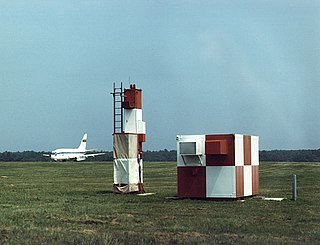
An instrument landing system localizer, or simply localizer, is a system of horizontal guidance in the instrument landing system, which is used to guide aircraft along the axis of the runway.

<span class="mw-page-title-main">Precision approach path indicator</span> Visual aid in aviation

A precision approach path indicator (PAPI) is a system of lights on the side of an airport runway threshold that provides visual descent guidance information during final approach. It is generally located on the left-hand side of the runway approximately 300 meters beyond the landing threshold of the runway.

<span class="mw-page-title-main">Instrument approach</span> Aircraft landing procedure

In aviation, an instrument approach or instrument approach procedure (IAP) is a series of predetermined maneuvers for the orderly transfer of an aircraft operating under instrument flight rules from the beginning of the initial approach to a landing, or to a point from which a landing may be made visually. These approaches are approved in the European Union by EASA and the respective country authorities and in the United States by the FAA or the United States Department of Defense for the military. The ICAO defines an instrument approach as, "a series of predetermined maneuvers by reference to flight instruments with specific protection from obstacles from the initial approach fix, or where applicable, from the beginning of a defined arrival route to a point from which a landing can be completed and thereafter, if landing is not completed, to a position at which holding or en route obstacle clearance criteria apply."

<span class="mw-page-title-main">Autoland</span> Automated aircraft landing procedure

In aviation, autoland describes a system that fully automates the landing procedure of an aircraft's flight, with the flight crew supervising the process. Such systems enable airliners to land in weather conditions that would otherwise be dangerous or impossible to operate in.

A blind approach beacon system or beam approach beacon system (BABS) is an automatic radar landing system developed in the early 1940s.

<span class="mw-page-title-main">Microwave landing system</span> All-weather, precision radio guidance system

The microwave landing system (MLS) is an all-weather, precision radio guidance system intended to be installed at large airports to assist aircraft in landing, including 'blind landings'. MLS enables an approaching aircraft to determine when it is aligned with the destination runway and on the correct glidepath for a safe landing. MLS was intended to replace or supplement the instrument landing systems (ILS). MLS has a number of operational advantages over ILS, including a wider selection of channels to avoid interference with nearby installations, excellent performance in all weather, a small "footprint" at the airports, and wide vertical and horizontal "capture" angles that allowed approaches from wider areas around the airport.

<span class="mw-page-title-main">Secondary surveillance radar</span> Radar system used in air traffic control

Secondary surveillance radar (SSR) is a radar system used in air traffic control (ATC), that unlike primary radar systems that measure the bearing and distance of targets using the detected reflections of radio signals, relies on targets equipped with a radar transponder, that reply to each interrogation signal by transmitting encoded data such as an identity code, the aircraft's altitude and further information depending on its chosen mode. SSR is based on the military identification friend or foe (IFF) technology originally developed during World War II, therefore the two systems are still compatible. Monopulse secondary surveillance radar (MSSR), Mode S, TCAS and ADS-B are similar modern methods of secondary surveillance.

<span class="mw-page-title-main">Precision approach radar</span> Type of radar guidance system

Precision approach radar (PAR) is a type of radar guidance system designed to provide lateral and vertical guidance to an aircraft pilot for landing, until the landing threshold is reached. Controllers monitoring the PAR displays observe each aircraft's position and issue instructions to the pilot that keep the aircraft on course and glidepath during final approach. After the aircraft reaches the decision height (DH) or decision altitude (DA), further guidance is advisory only. The overall concept is known as ground-controlled approach (GCA), and this name was also used to refer to the radar systems in the early days of its development.

<span class="mw-page-title-main">Marker beacon</span>

A marker beacon is a particular type of VHF radio beacon used in aviation, usually in conjunction with an instrument landing system (ILS), to give pilots a means to determine position along an established route to a destination such as a runway.
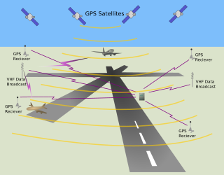
In aviation, a ground-controlled approach (GCA) is a type of service provided by air-traffic controllers whereby they guide aircraft to a safe landing, including in adverse weather conditions, based on primary radar images. Most commonly, a GCA uses information from either a precision approach radar or an airport surveillance radar. The term GCA may refer to any type of ground radar guided approach such as a PAR, PAR without glideslope or ASR. When both vertical and horizontal guidance from the PAR is given, the approach is termed a precision approach. If no PAR glidepath is given, even if PAR equipment is used for lateral guidance, it is considered a non-precision approach.

Space modulation is a radio amplitude modulation technique used in instrument landing systems (ILS) that incorporates the use of multiple antennas fed with various radio frequency powers and phases to create different depths of modulation within various volumes of three-dimensional airspace. This modulation method differs from internal modulation methods inside most other radio transmitters in that the phases and powers of the two individual signals mix within airspace, rather than in a modulator.

The AN/MPN is a mobile Ground-controlled approach radar first used during World War II. "MPN" is Joint Electronics Type Designation System nomenclature for (Ground) Mobile (M), Pulsed (P), Navigation aid (N).

<span class="mw-page-title-main">Inex-Adria Aviopromet Flight 450</span> 1975 aviation accident

Inex-Adria Aviopromet Flight 450, JP 450, was an international charter flight from Tivat in the Socialist Federal Republic of Yugoslavia to Prague, Czechoslovakia which crashed in the Prague suburb of Suchdol on October 30, 1975, at 09:20 AM. The McDonnell Douglas DC-9-32 with 115 passengers and 5 crew on board descended, under Instrument Meteorological Conditions (IMC), below defined Minimum Descent Altitude (MDA) during the final approach to Prague Ruzyně Airport RWY 25, entered a gorge above Vltava river, and was unable to outclimb the rising terrain. 75 of the 120 occupants died during the crash itself while 4 others died in Hospital. The accident remains the worst aviation disaster on the Czech Republic soil.

<span class="mw-page-title-main">Instrument landing system glide path</span> Aircraft guidance system

In aviation, Instrument landing system glide path, commonly referred to as a glide path (G/P) or glide slope (G/S), is "a system of vertical guidance embodied in the instrument landing system which indicates the vertical deviation of the aircraft from its optimum path of descent".
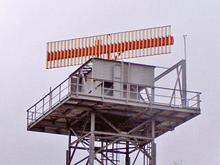
<span class="mw-page-title-main">Primary radar</span>

A Primary radar is a conventional radar sensor that illuminates a large portion of space with an electromagnetic wave and receives back the reflected waves from targets within that space. The term thus refers to a radar system used to detect and localize potentially non-cooperative targets. It is specific to the field of air traffic control where it is opposed to the secondary radar which receives additional information from the target's transponder.

References