
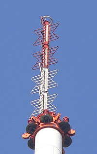
In telecommunications, a collinear antenna array is an array of dipole or quarter-wave antennas mounted in such a manner that the corresponding elements of each antenna are parallel and collinear; that is, they are located along a common axis.

A log-periodic antenna (LP), also known as a log-periodic array or log-periodic aerial, is a multi-element, directional antenna designed to operate over a wide band of frequencies. It was invented by John Dunlavy in 1952.

In antenna theory, a phased array usually means an electronically scanned array, a computer-controlled array of antennas which creates a beam of radio waves that can be electronically steered to point in different directions without moving the antennas.

In telecommunications and radar, a reflective array antenna is a class of directive antennas in which multiple driven elements are mounted in front of a flat surface designed to reflect the radio waves in a desired direction. They are a type of array antenna. They are often used in the VHF and UHF frequency bands. VHF examples are generally large and resemble a highway billboard, so they are sometimes called billboard antennas. Other names are bedspring array and bowtie array depending on the type of elements making up the antenna. The curtain array is a larger version used by shortwave radio broadcasting stations.

In radio engineering, an antenna or aerial is the interface between radio waves propagating through space and electric currents moving in metal conductors, used with a transmitter or receiver. In transmission, a radio transmitter supplies an electric current to the antenna's terminals, and the antenna radiates the energy from the current as electromagnetic waves. In reception, an antenna intercepts some of the power of a radio wave in order to produce an electric current at its terminals, that is applied to a receiver to be amplified. Antennas are essential components of all radio equipment.

Effective radiated power (ERP), synonymous with equivalent radiated power, is an IEEE standardized definition of directional radio frequency (RF) power, such as that emitted by a radio transmitter. It is the total power in watts that would have to be radiated by a half-wave dipole antenna to give the same radiation intensity as the actual source antenna at a distant receiver located in the direction of the antenna's strongest beam. ERP measures the combination of the power emitted by the transmitter and the ability of the antenna to direct that power in a given direction. It is equal to the input power to the antenna multiplied by the gain of the antenna. It is used in electronics and telecommunications, particularly in broadcasting to quantify the apparent power of a broadcasting station experienced by listeners in its reception area.

A Yagi–Uda antenna or simply Yagi antenna, is a directional antenna consisting of two or more parallel resonant antenna elements in an end-fire array; these elements are most often metal rods acting as half-wave dipoles. Yagi–Uda antennas consist of a single driven element connected to a radio transmitter and/or receiver through a transmission line, and additional "passive radiators" with no electrical connection, usually including one so-called reflector and any number of directors. It was invented in 1926 by Shintaro Uda of Tohoku Imperial University, Japan, with a lesser role played by his colleague Hidetsugu Yagi.

In radio communication, an omnidirectional antenna is a class of antenna which radiates equal radio power in all directions perpendicular to an axis, with power varying with angle to the axis, declining to zero on the axis. When graphed in three dimensions (see graph) this radiation pattern is often described as doughnut-shaped. Note that this is different from an isotropic antenna, which radiates equal power in all directions, having a spherical radiation pattern. Omnidirectional antennas oriented vertically are widely used for nondirectional antennas on the surface of the Earth because they radiate equally in all horizontal directions, while the power radiated drops off with elevation angle so little radio energy is aimed into the sky or down toward the earth and wasted. Omnidirectional antennas are widely used for radio broadcasting antennas, and in mobile devices that use radio such as cell phones, FM radios, walkie-talkies, wireless computer networks, cordless phones, GPS, as well as for base stations that communicate with mobile radios, such as police and taxi dispatchers and aircraft communications.

In radio and telecommunications a dipole antenna or doublet is the simplest and most widely used class of antenna. The dipole is any one of a class of antennas producing a radiation pattern approximating that of an elementary electric dipole with a radiating structure supporting a line current so energized that the current has only one node at each end. A dipole antenna commonly consists of two identical conductive elements such as metal wires or rods. The driving current from the transmitter is applied, or for receiving antennas the output signal to the receiver is taken, between the two halves of the antenna. Each side of the feedline to the transmitter or receiver is connected to one of the conductors. This contrasts with a monopole antenna, which consists of a single rod or conductor with one side of the feedline connected to it, and the other side connected to some type of ground. A common example of a dipole is the "rabbit ears" television antenna found on broadcast television sets.
In a multielement antenna array, the driven element or active element is the element in the antenna which is electrically connected to the receiver or transmitter. In a transmitting antenna it is driven or excited by the radio frequency current from the transmitter, and is the source of the radio waves. In a receiving antenna it collects the incoming radio waves for reception, and converts them to tiny oscillating electric currents, which are applied to the receiver. Multielement antennas like the Yagi typically consist of a driven element, connected to the receiver or transmitter through a feed line, and a number of other elements which are not driven, called parasitic elements. The driven element is often a dipole. The parasitic elements act as resonators and couple electromagnetically with the driven element, and serve to modify the radiation pattern of the antenna, directing the radio waves in one direction, increasing the gain of the antenna.

A slot antenna consists of a metal surface, usually a flat plate, with one or more holes or slots cut out. When the plate is driven as an antenna by an applied radio frequency current, the slot radiates electromagnetic waves in a way similar to a dipole antenna. The shape and size of the slot, as well as the driving frequency, determine the radiation pattern. Slot antennas are usually used at UHF and microwave frequencies at which wavelengths are small enough that the plate and slot are conveniently small. At these frequencies, the radio waves are often conducted by a waveguide, and the antenna consists of slots in the waveguide; this is called a slotted waveguide antenna. Multiple slots act as a directive array antenna and can emit a narrow fan-shaped beam of microwaves. They are used in standard laboratory microwave sources used for research, UHF television transmitting antennas, antennas on missiles and aircraft, sector antennas for cellular base stations, and particularly marine radar antennas. A slot antenna's main advantages are its size, design simplicity, and convenient adaptation to mass production using either waveguide or PC board technology.
Near vertical incidence skywave, or NVIS, is a skywave radio-wave propagation path that provides usable signals in the medium distances range — usually 0–650 km. It is used for military and paramilitary communications, broadcasting, especially in the tropics, and by radio amateurs for nearby contacts circumventing line-of-sight barriers. The radio waves travel near-vertically upwards into the ionosphere, where they are refracted back down and can be received within a circular region up to 650 km from the transmitter. If the frequency is too high, refraction is insufficient to return the signal to earth and if it is too low, absorption in the ionospheric D layer may reduce the signal strength.
A radio transmitter or receiver is connected to an antenna which emits or receives the radio waves. The antenna feed system or antenna feed is the cable or conductor, and other associated equipment, which connects the transmitter or receiver with the antenna and makes the two devices compatible. In a radio transmitter, the transmitter generates an alternating current of radio frequency, and the feed system feeds the current to the antenna, which converts the power in the current to radio waves. In a radio receiver, the incoming radio waves excite tiny alternating currents in the antenna, and the feed system delivers this current to the receiver, which processes the signal.
James R. Wait was a Canadian electrical engineer and engineering physicist. In 1977, he was elected as a member of National Academy of Engineering in Electronics, Communication & Information Systems Engineering for his contributions to electromagnetic propagation engineering as it affects communication and geophysical exploration.
A batwing or super turnstile antenna is a type of broadcasting antenna used at VHF and UHF frequencies, named for its distinctive shape which resembles a bat wing or bow tie. Stacked arrays of batwing antennas are used as television broadcasting antennas due to their omnidirectional characteristics. Batwing antennas generate a horizontally polarized signal. The advantage of the "batwing" design for television broadcasting is that it has a wide bandwidth. It was the first widely used television broadcasting antenna.
An antenna array is a set of multiple connected antennas which work together as a single antenna, to transmit or receive radio waves. The individual antennas are usually connected to a single receiver or transmitter by feedlines that feed the power to the elements in a specific phase relationship. The radio waves radiated by each individual antenna combine and superpose, adding together to enhance the power radiated in desired directions, and cancelling to reduce the power radiated in other directions. Similarly, when used for receiving, the separate radio frequency currents from the individual antennas combine in the receiver with the correct phase relationship to enhance signals received from the desired directions and cancel signals from undesired directions. More sophisticated array antennas may have multiple transmitter or receiver modules, each connected to a separate antenna element or group of elements.
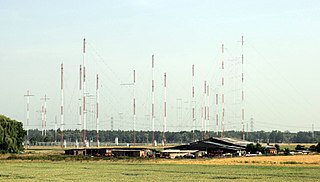
Curtain arrays are a class of large multielement directional radio transmitting wire antennas, used in the shortwave radio bands. They are a type of reflective array antenna, consisting of multiple wire dipole antennas, suspended in a vertical plane, often in front of a "curtain" reflector made of a flat vertical screen of many long parallel wires. These are suspended by support wires strung between pairs of tall steel towers, up to 90 m high. They are used for long-distance skywave transmission; they transmit a beam of radio waves at a shallow angle into the sky just above the horizon, which is reflected by the ionosphere back to Earth beyond the horizon. Curtain antennas are mostly used by international short wave radio stations to broadcast to large areas at transcontinental distances.

The self-complementary antenna (SCA) is a basic antenna for extremely broadband practical antennas. This antenna is an arbitrarily shaped antenna which is constituted with a half of an infinitely extended planar-sheet conductor such that the shape of its complementary structure is exactly identical, or "self-complementary" with that of the original structure with two terminals for the simplest case. The self-complementary antenna has constant input impedance independent of the source frequency and the shape of the structure.
An array is simply a group of objects, and the array factor is a measure of how much a specific characteristic changes because of the grouping. This phenomenon is observed when antennas are grouped together. The radiation pattern of the antenna group is considerably different from that of a single antenna. This is due to the constructive and destructive interference properties of radio waves. A well designed antenna array, allows the broadcast power to be directed to where it is needed most.
In radio systems, many different antenna types are used with specialized properties for particular applications. Antennas can be classified in various ways. The list below groups together antennas under common operating principles, following the way antennas are classified in many engineering textbooks.