End view showing metal insertsTwist-on connectors used in a junction boxTwist-on wire connectors
Twist-on wire connectors are a type of electrical connector used to fasten two or more low-voltage (or extra-low-voltage) electrical conductors. They are widely used in North America and several European countries in residential, commercial and industrial building power wiring, but are distrusted in some countries, due to early porcelain versions breaking apart, exposing bare conductors.[1]
Twist-on connectors are also known as wire nuts, wire connectors, cone connectors, or thimble connectors. In Canada, the trade name Marrette (see §History) is commonly used generically for connectors of any brand.
Description
Twist-on wire connectors are available in a variety of sizes and shapes. While their exterior covering is typically made from insulating plastic, their means of connection is a tapered coiled metal insert, which threads onto the wires and holds them securely. When such a connector is twisted onto the stripped ends of wires, the wires are drawn into the connector's metal insert and squeezed together inside it. Electrical continuity is maintained both by the direct twisted wire-to-wire contact and by contact with the metal insert.
Twist-on wire connectors are typically installed by hand. They may have external grooves to make them easier to handle and apply. Winglike extensions are commonly molded into higher quality connectors to reduce operator muscle fatigue when installing a large number of the connectors. Such extensions also allow these connectors to be installed with a common nut driver or a specialized tool.
Twist-on wire connectors are commonly color-coded to indicate the connector size and, hence, their capacity. They are commonly used as an alternative to terminal blocks or soldering of conductors, since they are quicker to install and, unlike soldered or crimped connections, allow easy subsequent removal for future modifications.
Twist-on connectors are not often used on wire gauges thicker than AWG #10 (5.26mm²), because such solid wires are too stiff to be reliably connected with this method. Set screw connectors, clamps or crimp connectors are used instead.
Twist-on connectors are not used in damp or vibration-prone locations, such as automotive or trailer applications.[2] Such applications use mechanically crimped connections or other methods which resist vibration and moisture.
Variants
Ceramic twist-on connectors are made for high-temperature applications, such as heating appliances.
Ordinary twist-on connectors are not rated for wet use (such as exposed outdoors or buried underground). Special gel-filled connectors must be used.
Twist-on wire connectors are not generally recommended for use with aluminum wire in the United States.[3] The U.S. Consumer Product Safety Commission disapproves wire nuts for aluminum wire; instead, special crimp connectors are called for, and as of 2011 the CPSC asserted qualified, second-preference approval of a certain kind of screw terminal.[4] In spite of this, several companies manufacture twist-on connectors, which they claim are designed and rated for use with aluminum conductors.[5] Specific twist-on wire connectors containing a conductive, anti-oxidant gel are registered for use on residential aluminum wiring in Canada, including when new copper wiring is connected to existing aluminum wiring.[6]
Special feedthrough twist-on wire connectors differ from standard wire connectors in that they have an additional opening at the top of the insulated cap. This allows a single-conductor bare wire to be pushed through the hole, forming a "pigtail" section which can be attached to a grounding screw. These feedthrough connectors are typically green, and are also called "screw-on grounding connectors".
Another specialized connector version has a permanently attached wire pigtail protruding from the top of the insulated cap. The pigtail may be unterminated, or it may end in a preinstalled spade lug. If colored white, it typically may be used for splicing neutral wires in a device box, while leaving a pigtail free for connection to a device (such as a receptacle). If colored green, the assembly is intended to be used as a grounding pigtail, similar to the feedthrough twist-on wire connectors without a permanently-attached wire.
History
William P. Marr emigrated from Scotland to Ontario, Canada early in the twentieth century. After settling in the Toronto area, he was employed as an electrician contractor for Ontario Hydro, converting gas-lit homes to electrical incandescent lighting.
At that time, the accepted practice for joining conductors was a process called “solder and tape”. Typically, a mechanic installed the insulated wires; then an electrician cleaned the exposed conductors, twisted them together, and dipped them into a pot of molten solder. After they cooled, the conductors were wrapped with insulating tape.
The process was time-consuming and potentially dangerous. Marr was injured when he spilled molten solder on himself. Seeking a safer, more efficient connection method, Marr, working in his home workshop, developed the first pressure-type wire connector. In 1914, he produced a set-screw version, the forerunner of the present-day twist-on connector used throughout North America.
Ceramic twist-on connectors from the beginning of the 20th century
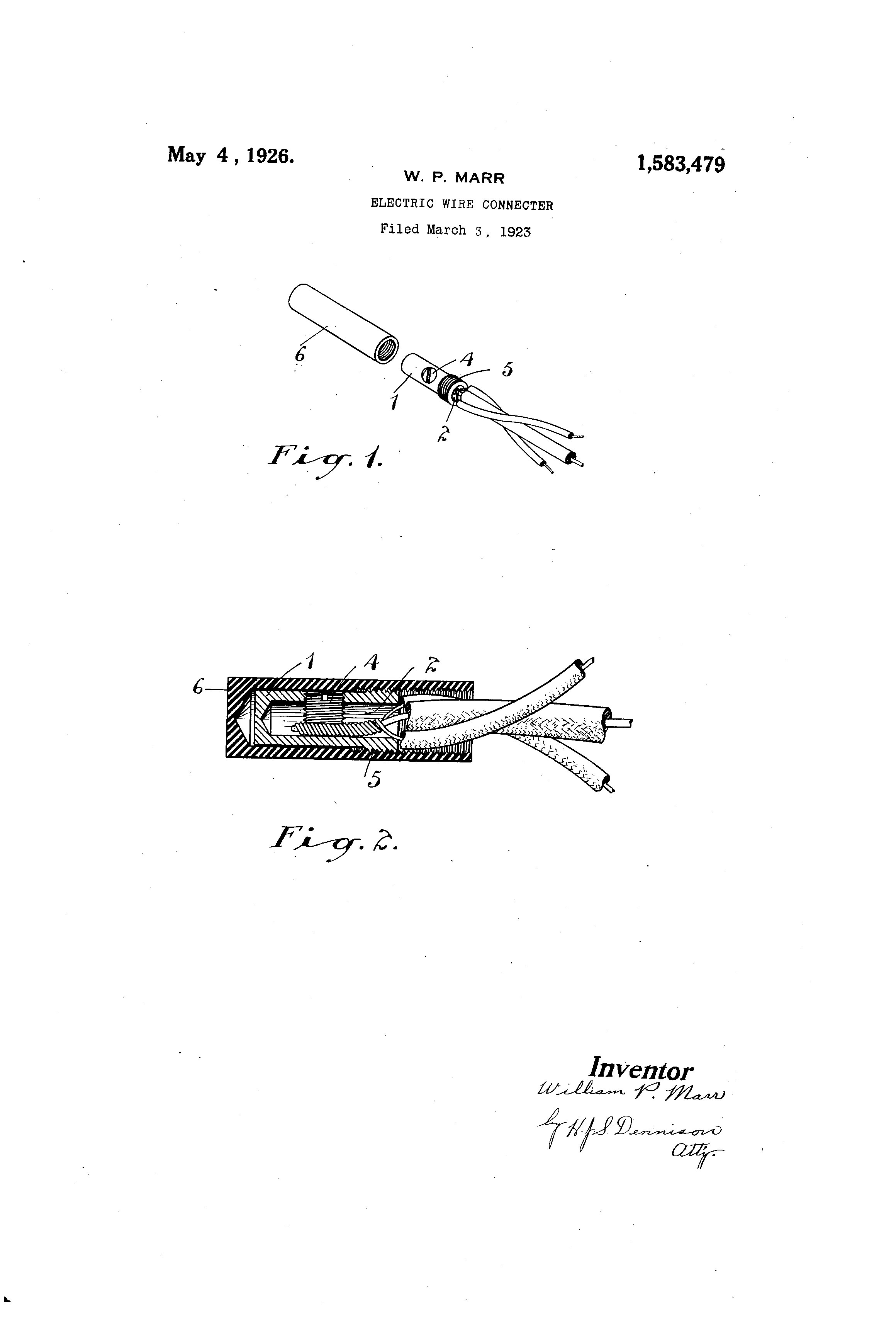
"Electric Wire Connecter" U.S. patent 1,583,479, Filed March 3, 1923, Patented May 4, 1926
However, this device used a "grub screw" to hold the pre-twisted conductors in position, as described in the Patent Application (and shown in the associated drawing):
In the use of this device, the electrician merely bares and twists his wire ends together. He then caps them with a sleeve which he rigidly secures in place by means of the grub screw, which on account of its long thread bearing may be tightened very securely without danger of stripping. The outer insulating tubular enclosure is then threaded on to the metallic cap and the job is completed.
A connector more closely resembling the present-day twist-on type was patented in Canada by Marr in 1931, and in the US in 1933.
"Wire Connecter" U.S. patent 1,896,322, Filed November 24, 1930, Patented February 7, 1933
Color code
This table shows the de facto standard color coding various manufacturers use[citation needed] to indicate the range of sizes of conductors that may be joined with twist-on wire connectors. There is a slight variation in capacity at the extremes between manufacturers.
Wire nut capacity for two equal-sized conductors[7][8][9]
This page is based on this Wikipedia article Text is available under the CC BY-SA 4.0 license; additional terms may apply. Images, videos and audio are available under their respective licenses.


