Variable speed wind turbine

Last updated

A variable speed wind turbine is one which is specifically designed to operate over a wide range of rotor speeds. It is in direct contrast to fixed speed wind turbine where the rotor speed is approximately constant. The reason to vary the rotor speed is to capture the maximum aerodynamic power in the wind, as the wind speed varies. The aerodynamic efficiency, or coefficient of power, for a fixed blade pitch angle is obtained by operating the wind turbine at the optimal tip-speed ratio as shown in the following graph.

Contents

Cplambdadiagram.jpg

Tip-speed ratio is given by the following expression,

where is the rotor speed (in radians per second), is the radius of the rotor, and is the wind speed. As the wind speed varies, the rotor speed must be varied to maintain peak efficiency.

Background

Before the need to connect wind turbines to the grid, turbines were fixed-speed. This was not a problem because turbines did not have to be synchronized with the frequency of the grid. [1]

All grid-connected wind turbines, from the first one in 1939 until the development of variable-speed grid-connected wind turbines in the 1970s, were fixed-speed wind turbines. As of 2003, nearly all grid-connected wind turbines operate at an exactly constant speed (synchronous generators) or within a few percents of constant speed (induction generators). [1]

History

The Gamma 60 wind turbine - a 1.5 MW two-bladed yaw control turbine, which is ongoing further development by Seawind Ocean Technology B.V., was the world's first variable speed wind turbine with a teeter hinge. [2]

Torque Rotor-speed diagrams

For a wind turbine, the power harvested is given by the following formula:

where is the aerodynamic power and is the density of the air. The power coefficient is a representation of how much of the available power in the wind is captured by the wind turbine and can be looked up in the graph above.

The torque, , on the rotor shaft is given by the ratio of the power extracted to the rotor speed:

Thus we can get the following expressions for torque and power:

and

From the above equation, we can construct a torque-speed diagram for a wind turbine. This consists of multiple curves: a constant power curve which plots the relationship between torque and rotor speed for constant power (green curve); constant wind speed curves, which plot the relationship between torque and rotor speed for constant wind speeds (dashed grey curves); and constant efficiency curves, which plot the relationship between torque and rotor speed for constant efficiencies, . [3] This diagram is presented below:

TRS for wind turbine.jpg

Notes

Green curve: Plot of power = rated power so that

Grey curve: Wind speed is assumed constant so that

Blue curve: Constant so that

Blade forces

For further details, see Blade Element Momentum Theory

Consider the following figure:

Apparent speed seen by rotor blade.jpg

This is the depiction of the apparent wind speed, as seen by a blade (left of figure). The apparent wind speed is influenced by both the free-stream velocity of the air, and the rotor speed. From this figure, we can see that both the angle and the apparent wind speed are functions of the rotor speed, . By extension, the lift and drag forces will also be functions of . This means that the axial and tangential forces that act on the blade vary with rotor speed. The force in the axial direction is given by the following formula:

Operating strategies for variable speed wind turbines

Stall regulated

As discussed earlier, a wind turbine would ideally operate at its maximum efficiency for below rated power. Once rated power has been hit, the power is limited. This is for two reasons: ratings on the drivetrain equipment, such as the generator; and second to reduce the loads on the blades. An operating strategy for a wind turbine can thus be divided into a sub-rated-power component, and a rated-power component.

Below rated power

Below rated power, the wind turbine will ideally operate in such a way that . On a Torque-rotor speed diagram, this looks as follows:

Stall regulated variable speed wind turbine TRS1.jpg

where the black line represents the initial section of the operating strategy for a variable speed stall-regulated wind turbine. Ideally, we would want to stay on the maximum efficiency curve until rated power is hit. However, as the rotor speed increases, the noise levels increase. To counter this, the rotor speed is not allowed to increase above a certain value. This is illustrated in the figure below:

Stall regulated variable speed wind turbine TRS2.jpg

Rated power and above

Once the wind speed has reached a certain level, called rated wind speed, the turbine should not be able to produce any greater levels of power for higher wind speeds. A stall-regulated variable speed wind turbine has no pitching mechanism. However, the rotor speed is variable. The rotor speed can either be increased or decreased by an appropriately designed controller. In reference to the figure illustrated in the blade forces section, it is evident that the angle between the apparent wind speed and the plane of rotation is dependent upon the rotor speed. This angle is termed the angle of attack.

The lift and drag co-efficients for an airfoil are related to the angle of attack. Specifically, for high angles of attack, an airfoil stalls. That is, the drag substantially increases. The lift and drag forces influence the power production of a wind turbine. This can be seen from an analysis of the forces acting on a blade as air interacts with the blade (see the following link). Thus, forcing the airfoil to stall can result in power limiting.

So it can be established that if the angle of attack needs to be increased to limit the power production of the wind turbine, the rotor speed must be reduced. Again, this can be seen from the figure in the blade forces section. It can also be seen from considering the torque-rotor speed diagram. In reference to the above torque-rotor speed diagram, by reducing the rotor speed at high wind speeds, the turbine enters the stall region, thus bringing some limiting to the power output.

Stall regulated variable speed wind turbine TRS.jpg

Pitch regulated

Pitch regulation thus allows the wind turbine to actively change the angle of attack of the air on the blades. This is preferred over a stall-regulated wind turbine as it enables far greater control of the power output.

Below rated power

Identical to the stall-regulated variable-speed wind turbine, the initial operating strategy is to operate on the curve. However, due to constraints such as noise levels, this is not possible for the full range of sub-rated wind speeds. Below the rated wind speed, the following operating strategy is employed:

Stall regulated variable speed wind turbine TRS2.jpg

Above rated power

Above the rated wind speed, the pitching mechanism is employed. This allows a good level of control over the angle of attack, thus control over the torque. The previous torque rotor-speed diagrams are all plots when the pitch angle, , is zero. A three dimensional plot can be produced which includes variations in pitch angle.

Ultimately, in the 2D plot, above rated wind speed, the turbine will operate at the point marked 'x' on the diagram below.

Pitch regulated variable speed wind turbine TRS3.jpg

Gearboxes

A variable speed may or may not have a gearbox, depending on the manufacturer's desires. Wind turbines without gearboxes are called direct-drive wind turbines. An advantage of a gearbox is that generators are typically designed to have the rotor rotating at a high speed within the stator. Direct drive wind turbines do not exhibit this feature. A disadvantage of a gearbox is reliability and failure rates. [4]

An example of a wind turbine without a gearbox is the Enercon E82. [5]

Generators

For variable speed wind turbines, one of two types of generators can be used: a DFIG (doubly fed induction generator) or an FRC (fully rated converter).

A DFIG generator draws reactive power from the transmission system; this can increase the vulnerability of a transmission system in the event of a failure. A DFIG configuration will require the generator to be a wound rotor; [6] squirrel cage rotors cannot be used for such a configuration.

A fully rated converter can either be an induction generator or a permanent magnet generator. Unlike the DFIG, the FRC can employ a squirrel cage rotor in the generator; an example of this is the Siemens SWT 3.6-107, which is termed the industry workhorse. [7] An example of a permanent magnet generator is the Siemens SWT-2.3-113. [8] A disadvantage of a permanent magnet generator is the cost of materials that need to be included. [9]

Grid Connections

Consider a variable speed wind turbine with a permanent magnet synchronous generator. The generator produces AC electricity. The frequency of the AC voltage generated by the wind turbine is a function of the speed of the rotor within the generator:

where is the rotor speed, is the number of poles in the generator, and is the frequency of the output Voltage. That is, as the wind speed varies, the rotor speed varies, and so the frequency of the Voltage varies. This form of electricity cannot be directly connected to a transmission system. Instead, it must be corrected such that its frequency is constant. For this, power converters are employed, which results in the de-coupling of the wind turbine from the transmission system. As more wind turbines are included in a national power system, the inertia is decreased. This means that the frequency of the transmission system is more strongly affected by the loss of a single generating unit.

Power converters

As already mentioned, the voltage generated by a variable speed wind turbine is non-grid compliant. In order to supply the transmission network with power from these turbines, the signal must be passed through a power converter, which ensures that the frequency of the voltage of the electricity being generated by the wind turbine is the frequency of the transmission system when it is transferred onto the transmission system. Power converters first convert the signal to DC, and then convert the DC signal to an AC signal. Techniques used include pulse width modulation.

Related Research Articles

Darrieus wind turbine Type of vertical axis wind turbine

The Darrieus wind turbine is a type of vertical axis wind turbine (VAWT) used to generate electricity from wind energy. The turbine consists of a number of curved aerofoil blades mounted on a rotating shaft or framework. The curvature of the blades allows the blade to be stressed only in tension at high rotating speeds. There are several closely related wind turbines that use straight blades. This design of the turbine was patented by Georges Jean Marie Darrieus, a French aeronautical engineer; filing for the patent was October 1, 1926. There are major difficulties in protecting the Darrieus turbine from extreme wind conditions and in making it self-starting.

Epicyclic gearing Two gears mounted so the center of one gear revolves around the center of the other

An epicyclic gear train consists of two gears mounted so that the center of one gear revolves around the center of the other. A carrier connects the centers of the two gears and rotates the planet and sun gears mesh so that their pitch circles roll without slip. A point on the pitch circle of the planet gear traces an epicycloid curve. In this simplified case, the sun gear is fixed and the planetary gear(s) roll around the sun gear.

Weierstrass elliptic function Class of mathematical functions

In mathematics, the Weierstrass elliptic functions are elliptic functions that take a particularly simple form. They are named for Karl Weierstrass. This class of functions are also referred to as ℘-functions and they are usually denoted by the symbol ℘, a uniquely fancy script p. They play an important role in the theory of elliptic functions. A ℘-function together with its derivative can be used to parameterize elliptic curves and they generate the field of elliptic functions with respect to a given period lattice.

Smith chart Graphical calculator or nomogram designed for electrical and electronics engineers specializing in radio frequency (RF) engineering to assist in solving problems with transmission lines and matching circuits

The Smith chart, invented by Phillip H. Smith (1905–1987) and independently by Mizuhashi Tosaku, is a graphical calculator or nomogram designed for electrical and electronics engineers specializing in radio frequency (RF) engineering to assist in solving problems with transmission lines and matching circuits. The Smith chart can be used to simultaneously display multiple parameters including impedances, admittances, reflection coefficients, scattering parameters, noise figure circles, constant gain contours and regions for unconditional stability, including mechanical vibrations analysis. The Smith chart is most frequently used at or within the unity radius region. However, the remainder is still mathematically relevant, being used, for example, in oscillator design and stability analysis. While the use of paper Smith charts for solving the complex mathematics involved in matching problems has been largely replaced by software based methods, the Smith chart is still a very useful method of showing how RF parameters behave at one or more frequencies, an alternative to using tabular information. Thus most RF circuit analysis software includes a Smith chart option for the display of results and all but the simplest impedance measuring instruments can plot measured results on a Smith chart display.

Savonius wind turbine

Savonius wind turbines are a type of vertical-axis wind turbine (VAWT), used for converting the force of the wind into torque on a rotating shaft. The turbine consists of a number of aerofoils, usually—but not always—vertically mounted on a rotating shaft or framework, either ground stationed or tethered in airborne systems.

In fluid dynamics, dispersion of water waves generally refers to frequency dispersion, which means that waves of different wavelengths travel at different phase speeds. Water waves, in this context, are waves propagating on the water surface, with gravity and surface tension as the restoring forces. As a result, water with a free surface is generally considered to be a dispersive medium.

Damping is an influence within or upon an oscillatory system that has the effect of reducing or preventing its oscillation. In physical systems, damping is produced by processes that dissipate the energy stored in the oscillation. Examples include viscous drag in mechanical systems, resistance in electronic oscillators, and absorption and scattering of light in optical oscillators. Damping not based on energy loss can be important in other oscillating systems such as those that occur in biological systems and bikes. Not to be confused with friction, which is a dissipative force acting on a system. Friction can cause or be a factor of damping.

In classical mechanics, the Hannay angle is a mechanics analogue of the whirling geometric phase. It was named after John Hannay of the University of Bristol, UK. Hannay first described the angle in 1985, extending the ideas of the recently formalized Berry phase to classical mechanics.

Wind turbine design Process of defining the form of wind turbine systems

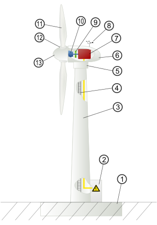
Wind turbine design is the process of defining the form and configuration of a wind turbine to extract energy from the wind. An installation consists of the systems needed to capture the wind's energy, point the turbine into the wind, convert mechanical rotation into electrical power, and other systems to start, stop, and control the turbine.

The tip-speed ratio, λ, or TSR for wind turbines is the ratio between the tangential speed of the tip of a blade and the actual speed of the wind, . The tip-speed ratio is related to efficiency, with the optimum varying with blade design. Higher tip speeds result in higher noise levels and require stronger blades due to larger centrifugal forces.

Wind turbine Machine that converts wind energy into electrical energy

A wind turbine is a device that converts the wind's kinetic energy into electrical energy. Hundreds of thousands of large turbines, in installations known as wind farms, now generate over 650 gigawatts of power, with 60 GW added each year. They are an increasingly important source of intermittent renewable energy, and are used in many countries to lower energy costs and reduce reliance on fossil fuels. One study claimed that, as of 2009, wind had the "lowest relative greenhouse gas emissions, the least water consumption demands and... the most favourable social impacts" compared to photovoltaic, hydro, geothermal, coal and gas.

Wind-turbine aerodynamics

The primary application of wind turbines is to generate energy using the wind. Hence, the aerodynamics is a very important aspect of wind turbines. Like most machines, there are many different types of wind turbines, all of them based on different energy extraction concepts.

A permanent magnet synchronous generator is a generator where the excitation field is provided by a permanent magnet instead of a coil. The term synchronous refers here to the fact that the rotor and magnetic field rotate with the same speed, because the magnetic field is generated through a shaft mounted permanent magnet mechanism and current is induced into the stationary armature.

Advance ratio Ratio of freestream speed to tip speed

In aeronautics and marine hydrodynamics, the advance ratio is the ratio of the freestream fluid speed to the propeller, rotor, or cyclorotor tip speed. When a propeller-driven vehicle is moving at high speed relative to the fluid, or the propeller is rotating slowly, the advance ratio of its propeller(s) is a high number; and when it is moving at low speed, or the propeller is rotating at high speed, the advance ratio is a low number. The advance ratio is a useful non-dimensional velocity in helicopter and propeller theory, since propellers and rotors will experience the same angle of attack on every blade airfoil section at the same advance ratio regardless of actual forward speed. It is the inverse of the tip speed ratio used for wind turbines.

Envelope (waves)

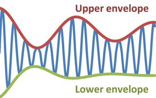
In physics and engineering, the envelope of an oscillating signal is a smooth curve outlining its extremes. The envelope thus generalizes the concept of a constant amplitude into an instantaneous amplitude. The figure illustrates a modulated sine wave varying between an upper envelope and a lower envelope. The envelope function may be a function of time, space, angle, or indeed of any variable.

Blade element momentum theory is a theory that combines both blade element theory and momentum theory. It is used to calculate the local forces on a propeller or wind-turbine blade. Blade element theory is combined with momentum theory to alleviate some of the difficulties in calculating the induced velocities at the rotor.

The loads on both horizontal axis wind turbines (HAWTs) and vertical axis wind turbines (VAWTs) are cyclic; that is, the thrust and torque acting on the blades is dependent on where the blade is. In a horizontal axis wind turbine, both the apparent wind speed seen by the blade and the angle of attack depend on the position of the blade. This phenomenon is described as rotational sampling. This article will provide an insight into the cyclic nature of the loads that arise because of rotational sampling for a horizontal axis wind turbine.

A power system consists of a number of synchronous machines operating synchronously under all operating conditions. Under normal operating conditions, the relative position of the rotor axis and the resultant magnetic field axis is fixed. The angle between the two is known as the power angle or torque angle. During any disturbance, the rotor decelerates or accelerates with respect to the synchronously rotating air gap magnetomotive force, creating relative motion. The equation describing the relative motion is known as the swing equation, which is a non-linear second order differential equation that describes the swing of the rotor of synchronous machine. The power exchange between the mechanical rotor and the electrical grid due to the rotor swing is called Inertial response.

Wide-area damping control (WADC) is a class of automatic control systems used to provide stability augmentation to modern electrical power systems known as smart grids. Actuation for the controller is provided via modulation of capable active or reactive power devices throughout the grid. Such actuators are most commonly previously-existing power system devices, such as high-voltage DC (HVDC) transmission lines and static VAR compensators (SVCs) which serve primary purposes not directly related to the WADC application. However, damping may be achieved with the utilization of other devices installed with the express purpose of stability augmentation, including energy storage technologies. Wide-area instability of a large electrical grid unequipped with a WADC is the result of the loss of generator rotor synchronicity and is typically envisioned as a generator oscillating with an undamped exponential trajectory as the result of insufficient damping torque.

Vertical-axis wind turbine Type of wind turbine

A vertical-axis wind turbine (VAWT) is a type of wind turbine where the main rotor shaft is set transverse to the wind while the main components are located at the base of the turbine. This arrangement allows the generator and gearbox to be located close to the ground, facilitating service and repair. VAWTs do not need to be pointed into the wind, which removes the need for wind-sensing and orientation mechanisms. Major drawbacks for the early designs included the significant torque variation or "ripple" during each revolution, and the large bending moments on the blades. Later designs addressed the torque ripple issue by sweeping the blades helically. Savonius vertical-axis wind turbines (VAWT) are not widespread, but their simplicity and better performance in disturbed flow-fields, compared to small horizontal-axis wind turbines (HAWT) make them a good alternative for distributed generation devices in urban environment.

References

  1. 1 2 P. W. Carlin, A. S. Laxson, and E. B. Muljadi. "The History and State of the Art of Variable-Speed Wind Turbine Technology". 2003. p. 130-131.
  2. Carlin, P.W.; Laxson, A.S.; Muljadi, E.B. "The History and State of the Art of Variable-Speed Wind Turbine Technology". NREL. National Renewable Energy Laboratory. Retrieved February 1, 2001.
  3. "Archived copy" (PDF). Archived from the original (PDF) on 2021-07-03. Retrieved 2017-09-17.{{cite web}}: CS1 maint: archived copy as title (link)
  4. http://mragheb.com/Wind%20Power%20Gearbox%20Technologies.pdf [ bare URL PDF ]
  5. http://www.enercon.de/en-en/64.htm
  6. http://www.4thintegrationconference.com/second/downloads/Anaya%20Trans%20Tutorial%20Talk.pdf [ bare URL PDF ]
  7. http://www.energy.siemens.com/nl/pool/hq/power-generation/renewables/wind-power/wind%20turbines/E50001-W310-A103-V6-4A00_WS_SWT_3_6_107_US.pdf [ dead link ]
  8. http://www.energy.siemens.com/us/pool/hq/power-generation/wind-power/E50001-W310-A174-X-4A00_WS_SWT-2.3-113_US.pdf [ dead link ]
  9. http://www.rechargenews.com/wind/article1292870.ece