
An electrical network is an interconnection of electrical components or a model of such an interconnection, consisting of electrical elements. An electrical circuit is a network consisting of a closed loop, giving a return path for the current. Linear electrical networks, a special type consisting only of sources, linear lumped elements, and linear distributed elements, have the property that signals are linearly superimposable. They are thus more easily analyzed, using powerful frequency domain methods such as Laplace transforms, to determine DC response, AC response, and transient response.
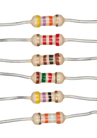
A resistor is a passive two-terminal electrical component that implements electrical resistance as a circuit element. In electronic circuits, resistors are used to reduce current flow, adjust signal levels, to divide voltages, bias active elements, and terminate transmission lines, among other uses. High-power resistors that can dissipate many watts of electrical power as heat may be used as part of motor controls, in power distribution systems, or as test loads for generators. Fixed resistors have resistances that only change slightly with temperature, time or operating voltage. Variable resistors can be used to adjust circuit elements, or as sensing devices for heat, light, humidity, force, or chemical activity.
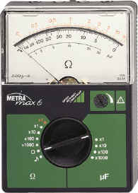
An ohmmeter is an electrical instrument that measures electrical resistance. Multimeters also function as ohmmeters when in resistance-measuring mode. An ohmmeter applies current to the circuit or component whose resistance is to be measured. It then measures the resulting voltage and calculates the resistance using Ohm’s law .

In electrical engineering, impedance is the opposition to alternating current presented by the combined effect of resistance and reactance in a circuit.

A negative-feedback amplifier is an electronic amplifier that subtracts a fraction of its output from its input, so that negative feedback opposes the original signal. The applied negative feedback can improve its performance and reduces sensitivity to parameter variations due to manufacturing or environment. Because of these advantages, many amplifiers and control systems use negative feedback.
In electronics, a linear regulator is a voltage regulator used to maintain a steady voltage. The resistance of the regulator varies in accordance with both the input voltage and the load, resulting in a constant voltage output. The regulating circuit varies its resistance, continuously adjusting a voltage divider network to maintain a constant output voltage and continually dissipating the difference between the input and regulated voltages as waste heat. By contrast, a switching regulator uses an active device that switches on and off (oscilates) to maintain an average value of output. Because the regulated voltage of a linear regulator must always be lower than input voltage, efficiency is limited and the input voltage must be high enough to always allow the active device to drop some voltage.

As originally stated in terms of direct-current resistive circuits only, Thévenin's theorem states that "Any linear electrical network containing only voltage sources, current sources and resistances can be replaced at terminals A–B by an equivalent combination of a voltage source Vth in a series connection with a resistance Rth."

Two-terminal components and electrical networks can be connected in series or parallel. The resulting electrical network will have two terminals, and itself can participate in a series or parallel topology. Whether a two-terminal "object" is an electrical component or an electrical network is a matter of perspective. This article will use "component" to refer to a two-terminal "object" that participate in the series/parallel networks.

In electronics, a common-base amplifier is one of three basic single-stage bipolar junction transistor (BJT) amplifier topologies, typically used as a current buffer or voltage amplifier.
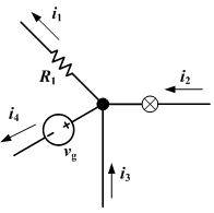
Kirchhoff's circuit laws are two equalities that deal with the current and potential difference in the lumped element model of electrical circuits. They were first described in 1845 by German physicist Gustav Kirchhoff. This generalized the work of Georg Ohm and preceded the work of James Clerk Maxwell. Widely used in electrical engineering, they are also called Kirchhoff's rules or simply Kirchhoff's laws. These laws can be applied in time and frequency domains and form the basis for network analysis.
In electrical engineering and electronics, a network is a collection of interconnected components. Network analysis is the process of finding the voltages across, and the currents through, all network components. There are many techniques for calculating these values; however, for the most part, the techniques assume linear components. Except where stated, the methods described in this article are applicable only to linear network analysis.

A current source is an electronic circuit that delivers or absorbs an electric current which is independent of the voltage across it.
In electronics, a shunt is a device that creates a low-resistance path for electric current, to allow it to pass around another point in the circuit. The origin of the term is in the verb 'to shunt' meaning to turn away or follow a different path.
In electric circuits analysis, nodal analysis, node-voltage analysis, or the branch current method is a method of determining the voltage between "nodes" in an electrical circuit in terms of the branch currents.
Mathematical methods are integral to the study of electronics.
In electronics, voltage drop is the decrease of electric potential along the path of a current flowing in a circuit. Voltage drops in the internal resistance of the source, across conductors, across contacts, and across connectors are undesirable because some of the energy supplied is dissipated. The voltage drop across the load is proportional to the power available to be converted in that load to some other useful form of energy.
The negative impedance converter (NIC) is an active circuit which injects energy into circuits in contrast to an ordinary load that consumes energy from them. This is achieved by adding or subtracting excessive varying voltage in series to the voltage drop across an equivalent positive impedance. This reverses the voltage polarity or the current direction of the port and introduces a phase shift of 180° (inversion) between the voltage and the current for any signal generator. The two versions obtained are accordingly a negative impedance converter with voltage inversion (VNIC) and a negative impedance converter with current inversion (INIC). The basic circuit of an INIC and its analysis is shown below.

In electronics, a current divider is a simple linear circuit that produces an output current (IX) that is a fraction of its input current (IT). Current division refers to the splitting of current between the branches of the divider. The currents in the various branches of such a circuit will always divide in such a way as to minimize the total energy expended.
A resistor ladder is an electrical circuit made from repeating units of resistors. Two configurations are discussed below, a string resistor ladder and an R-2R ladder.
The topology of an electronic circuit is the form taken by the network of interconnections of the circuit components. Different specific values or ratings of the components are regarded as being the same topology. Topology is not concerned with the physical layout of components in a circuit, nor with their positions on a circuit diagram; similarly to the mathematic concept of topology, it is only concerned with what connections exist between the components. There may be numerous physical layouts and circuit diagrams that all amount to the same topology.