
A magnetic field is a physical field that describes the magnetic influence on moving electric charges, electric currents, and magnetic materials. A moving charge in a magnetic field experiences a force perpendicular to its own velocity and to the magnetic field. A permanent magnet's magnetic field pulls on ferromagnetic materials such as iron, and attracts or repels other magnets. In addition, a nonuniform magnetic field exerts minuscule forces on "nonmagnetic" materials by three other magnetic effects: paramagnetism, diamagnetism, and antiferromagnetism, although these forces are usually so small they can only be detected by laboratory equipment. Magnetic fields surround magnetized materials, electric currents, and electric fields varying in time. Since both strength and direction of a magnetic field may vary with location, it is described mathematically by a function assigning a vector to each point of space, called a vector field.

Electromagnetic or magnetic induction is the production of an electromotive force (emf) across an electrical conductor in a changing magnetic field.

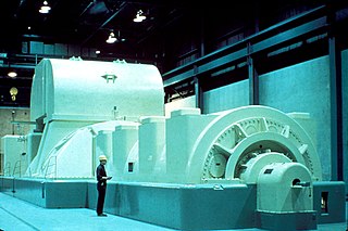
An electric motor is a machine that converts electrical energy into mechanical energy. Most electric motors operate through the interaction between the motor's magnetic field and electric current in a wire winding to generate force in the form of torque applied on the motor's shaft. An electric generator is mechanically identical to an electric motor, but operates in reverse, converting mechanical energy into electrical energy.
In electricity generation, a generator is a device that converts motion-based power or fuel-based power into electric power for use in an external circuit. Sources of mechanical energy include steam turbines, gas turbines, water turbines, internal combustion engines, wind turbines and even hand cranks. The first electromagnetic generator, the Faraday disk, was invented in 1831 by British scientist Michael Faraday. Generators provide nearly all the power for electrical grids.

A stepper motor, also known as step motor or stepping motor, is a Brushless DC electric motor that rotates in a series of small and discrete angular steps. Stepper motors can be set to any given step position without needing a position sensor for feedback. The step position can be rapidly increased or decreased to create continuous rotation, or the motor can be ordered to actively hold its position at one given step. Motors vary in size, speed, step resolution, and torque.

An alternator is an electrical generator that converts mechanical energy to electrical energy in the form of alternating current. For reasons of cost and simplicity, most alternators use a rotating magnetic field with a stationary armature. Occasionally, a linear alternator or a rotating armature with a stationary magnetic field is used. In principle, any AC electrical generator can be called an alternator, but usually, the term refers to small rotating machines driven by automotive and other internal combustion engines.

An induction motor or asynchronous motor is an AC electric motor in which the electric current in the rotor that produces torque is obtained by electromagnetic induction from the magnetic field of the stator winding. An induction motor therefore needs no electrical connections to the rotor. An induction motor's rotor can be either wound type or squirrel-cage type.
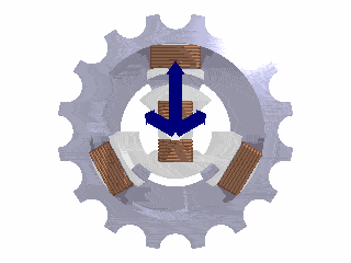
A rotating magnetic field (RMF) is the resultant magnetic field produced by a system of coils symmetrically placed and supplied with polyphase currents. A rotating magnetic field can be produced by a poly-phase (two or more phases) current or by a single phase current provided that, in the latter case, two field windings are supplied and are so designed that the two resulting magnetic fields generated thereby are out of phase.

A DC motor is an electrical motor that uses direct current (DC) to produce mechanical force. The most common types rely on magnetic forces produced by currents in the coils. Nearly all types of DC motors have some internal mechanism, either electromechanical or electronic, to periodically change the direction of current in part of the motor.
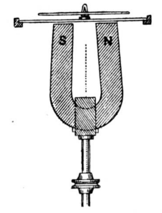
Barlow's wheel was an early demonstration of a homopolar motor, designed and built by English mathematician and physicist, Peter Barlow in 1822. It consists of a star-shaped wheel free to turn suspended over a trough of the liquid metal mercury, with the points dipping into the mercury, between the poles of a horseshoe magnet. A DC electric current passes from the hub of the wheel, through the wheel into the mercury and out through an electrical contact dipping into the mercury. The Lorentz force of the magnetic field on the moving charges in the wheel causes the wheel to rotate. The presence of serrations on the wheel is unnecessary and the apparatus will work with a round metal disk, usually made of copper.

In electrical engineering, the armature is the winding of an electric machine which carries alternating current. The armature windings conduct AC even on DC machines, due to the commutator action or due to electronic commutation, as in brushless DC motors. The armature can be on either the rotor or the stator, depending on the type of electric machine.
A homopolar motor is a direct current electric motor with two magnetic poles, the conductors of which always cut unidirectional lines of magnetic flux by rotating a conductor around a fixed axis so that the conductor is at right angles to a static magnetic field. The resulting force being continuous in one direction, the homopolar motor needs no commutator but still requires slip rings. The name homopolar indicates that the electrical polarity of the conductor and the magnetic field poles do not change.

A field coil is an electromagnet used to generate a magnetic field in an electro-magnetic machine, typically a rotating electrical machine such as a motor or generator. It consists of a coil of wire through which a current flows.
A repulsion motor is a type of electric motor which runs on alternating current (AC). It was formerly used as a traction motor for electric trains but has been superseded by other types of motors. Repulsion motors are classified as single phase motors.

An AC motor is an electric motor driven by an alternating current (AC). The AC motor commonly consists of two basic parts, an outside stator having coils supplied with alternating current to produce a rotating magnetic field, and an inside rotor attached to the output shaft producing a second rotating magnetic field. The rotor magnetic field may be produced by permanent magnets, reluctance saliency, or DC or AC electrical windings.

The rotor is a moving component of an electromagnetic system in the electric motor, electric generator, or alternator. Its rotation is due to the interaction between the windings and magnetic fields which produces a torque around the rotor's axis.

A dynamo is an electrical generator that creates direct current using a commutator. Dynamos were the first electrical generators capable of delivering power for industry, and the foundation upon which many other later electric-power conversion devices were based, including the electric motor, the alternating-current alternator, and the rotary converter.
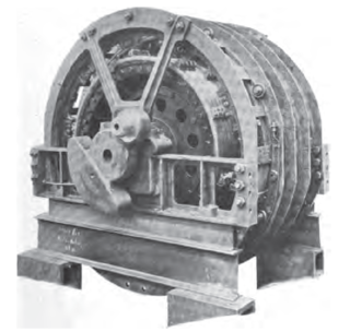
In electrical engineering, electric machine is a general term for machines using electromagnetic forces, such as electric motors, electric generators, and others. They are electromechanical energy converters: an electric motor converts electricity to mechanical power while an electric generator converts mechanical power to electricity. The moving parts in a machine can be rotating or linear. While transformers are occasionally called "static electric machines", since they do not have moving parts, generally they are not considered "machines", but as electrical devices "closely related" to the electrical machines.
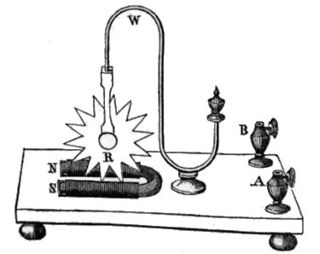
Arago's rotations is an observable magnetic phenomenon that involves the interactions between a magnetized needle and a moving metal disk. The effect was discovered by François Arago in 1824. At the time of their discovery, Arago's rotations were surprising effects that were difficult to explain. In 1831, Michael Faraday introduced the theory of electromagnetic induction, which explained how the effects happen in detail.
In 1885, Galileo Ferraris demonstrated an induction motor that also involved using two pairs of electromagnets to create a rotating magnetic field, though he did this independently of Baily. His motor more closely resembled modern ones in that the electromagnets surrounded a cylinder. More significantly, however, he proposed creating a true rotating magnetic field for it by supplying two sine wave alternating currents 90° apart. He gave his first public demonstration of the motor in 1888.

