
The characteristic impedance or surge impedance (usually written Z0) of a uniform transmission line is the ratio of the amplitudes of voltage and current of a wave travelling in one direction along the line in the absence of reflections in the other direction. Equivalently, it can be defined as the input impedance of a transmission line when its length is infinite. Characteristic impedance is determined by the geometry and materials of the transmission line and, for a uniform line, is not dependent on its length. The SI unit of characteristic impedance is the ohm.
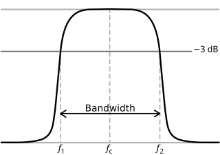
In physics and electrical engineering, a cutoff frequency, corner frequency, or break frequency is a boundary in a system's frequency response at which energy flowing through the system begins to be reduced rather than passing through.
The propagation constant of a sinusoidal electromagnetic wave is a measure of the change undergone by the amplitude and phase of the wave as it propagates in a given direction. The quantity being measured can be the voltage, the current in a circuit, or a field vector such as electric field strength or flux density. The propagation constant itself measures the dimensionless change in magnitude or phase per unit length. In the context of two-port networks and their cascades, propagation constant measures the change undergone by the source quantity as it propagates from one port to the next.

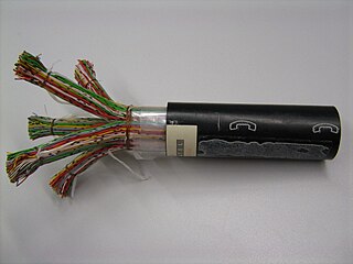
In electrical engineering, a transmission line is a specialized cable or other structure designed to conduct electromagnetic waves in a contained manner. The term applies when the conductors are long enough that the wave nature of the transmission must be taken into account. This applies especially to radio-frequency engineering because the short wavelengths mean that wave phenomena arise over very short distances. However, the theory of transmission lines was historically developed to explain phenomena on very long telegraph lines, especially submarine telegraph cables.

In electrical engineering, impedance is the opposition to alternating current presented by the combined effect of resistance and reactance in a circuit.
Chebyshev filters are analog or digital filters that have a steeper roll-off than Butterworth filters, and have either passband ripple or stopband ripple. Chebyshev filters have the property that they minimize the error between the idealized and the actual filter characteristic over the operating frequency range of the filter, but they achieve this with ripples in the passband. This type of filter is named after Pafnuty Chebyshev because its mathematical characteristics are derived from Chebyshev polynomials. Type I Chebyshev filters are usually referred to as "Chebyshev filters", while type II filters are usually called "inverse Chebyshev filters". Because of the passband ripple inherent in Chebyshev filters, filters with a smoother response in the passband but a more irregular response in the stopband are preferred for certain applications.

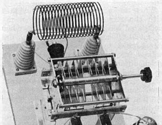
An LC circuit, also called a resonant circuit, tank circuit, or tuned circuit, is an electric circuit consisting of an inductor, represented by the letter L, and a capacitor, represented by the letter C, connected together. The circuit can act as an electrical resonator, an electrical analogue of a tuning fork, storing energy oscillating at the circuit's resonant frequency.

A quartz crystal microbalance (QCM) measures a mass variation per unit area by measuring the change in frequency of a quartz crystal resonator. The resonance is disturbed by the addition or removal of a small mass due to oxide growth/decay or film deposition at the surface of the acoustic resonator. The QCM can be used under vacuum, in gas phase and more recently in liquid environments. It is useful for monitoring the rate of deposition in thin-film deposition systems under vacuum. In liquid, it is highly effective at determining the affinity of molecules to surfaces functionalized with recognition sites. Larger entities such as viruses or polymers are investigated as well. QCM has also been used to investigate interactions between biomolecules. Frequency measurements are easily made to high precision ; hence, it is easy to measure mass densities down to a level of below 1 μg/cm2. In addition to measuring the frequency, the dissipation factor is often measured to help analysis. The dissipation factor is the inverse quality factor of the resonance, Q−1 = w/fr ; it quantifies the damping in the system and is related to the sample's viscoelastic properties.
A transmission line which meets the Heaviside condition, named for Oliver Heaviside (1850–1925), and certain other conditions can transmit signals without dispersion and without distortion. The importance of the Heaviside condition is that it showed the possibility of dispersionless transmission of telegraph signals.In some cases, the performance of a transmission line can be improved by adding inductive loading to the cable.
The telegrapher's equations are a set of two coupled, linear equations that predict the voltage and current distributions on a linear electrical transmission line. The equations are important because they allow transmission lines to be analyzed using circuit theory. The equations and their solutions are applicable from 0 Hz to frequencies at which the transmission line structure can support higher order non-TEM modes. The equations can be expressed in both the time domain and the frequency domain. In the time domain the independent variables are distance and time. The resulting time domain equations are partial differential equations of both time and distance. In the frequency domain the independent variables are distance and either frequency, , or complex frequency, . The frequency domain variables can be taken as the Laplace transform or Fourier transform of the time domain variables or they can be taken to be phasors. The resulting frequency domain equations are ordinary differential equations of distance. An advantage of the frequency domain approach is that differential operators in the time domain become algebraic operations in frequency domain.
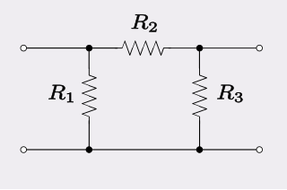
The Π pad is a specific type of attenuator circuit in electronics whereby the topology of the circuit is formed in the shape of the Greek capital letter pi (Π).

In electrochemistry, a Randles circuit is an equivalent electrical circuit that consists of an active electrolyte resistance RS in series with the parallel combination of the double-layer capacitance Cdl and an impedance of a faradaic reaction. It is commonly used in electrochemical impedance spectroscopy (EIS) for interpretation of impedance spectra, often with a constant phase element (CPE) replacing the double layer capacity. The Randles equivalent circuit is one of the simplest possible models describing processes at the electrochemical interface. In real electrochemical systems, impedance spectra are usually more complicated and, thus, the Randles circuit may not give appropriate results.
Constant k filters, also k-type filters, are a type of electronic filter designed using the image method. They are the original and simplest filters produced by this methodology and consist of a ladder network of identical sections of passive components. Historically, they are the first filters that could approach the ideal filter frequency response to within any prescribed limit with the addition of a sufficient number of sections. However, they are rarely considered for a modern design, the principles behind them having been superseded by other methodologies which are more accurate in their prediction of filter response.

The gyrator–capacitor model - sometimes also the capacitor-permeance model - is a lumped-element model for magnetic circuits, that can be used in place of the more common resistance–reluctance model. The model makes permeance elements analogous to electrical capacitance rather than electrical resistance. Windings are represented as gyrators, interfacing between the electrical circuit and the magnetic model.
The primary line constants are parameters that describe the characteristics of conductive transmission lines, such as pairs of copper wires, in terms of the physical electrical properties of the line. The primary line constants are only relevant to transmission lines and are to be contrasted with the secondary line constants, which can be derived from them, and are more generally applicable. The secondary line constants can be used, for instance, to compare the characteristics of a waveguide to a copper line, whereas the primary constants have no meaning for a waveguide.
The Warburg coefficient is the diffusion coefficient of ions in solution, associated to the Warburg element, ZW. The Warburg coefficient has units of
An RLC circuit is an electrical circuit consisting of a resistor (R), an inductor (L), and a capacitor (C), connected in series or in parallel. The name of the circuit is derived from the letters that are used to denote the constituent components of this circuit, where the sequence of the components may vary from RLC.
In thermal quantum field theory, the Matsubara frequency summation is a technique used to simplify calculations involving Euclidean path integrals.
A frequency-selective surface (FSS) is any thin, repetitive surface designed to reflect, transmit or absorb electromagnetic fields based on the frequency of the field. In this sense, an FSS is a type of optical filter or metal-mesh optical filters in which the filtering is accomplished by virtue of the regular, periodic pattern on the surface of the FSS. Though not explicitly mentioned in the name, FSS's also have properties which vary with incidence angle and polarization as well - these are unavoidable consequences of the way in which FSS's are constructed. Frequency-selective surfaces have been most commonly used in the radio signals of the electromagnetic spectrum and find use in applications as diverse as the aforementioned microwave oven, antenna radomes and modern metamaterials. Sometimes frequency selective surfaces are referred to simply as periodic surfaces and are a 2-dimensional analog of the new periodic volumes known as photonic crystals.
In fluid dynamics, Stokes problem also known as Stokes second problem or sometimes referred to as Stokes boundary layer or Oscillating boundary layer is a problem of determining the flow created by an oscillating solid surface, named after Sir George Stokes. This is considered one of the simplest unsteady problems that has an exact solution for the Navier–Stokes equations. In turbulent flow, this is still named a Stokes boundary layer, but now one has to rely on experiments, numerical simulations or approximate methods in order to obtain useful information on the flow.


