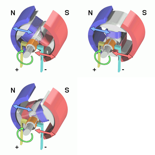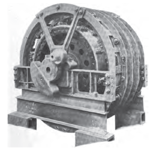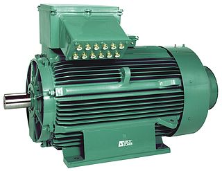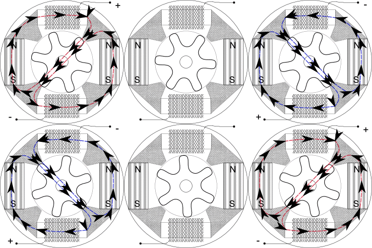
An electric motor is an electrical machine that converts electrical energy into mechanical energy. Most electric motors operate through the interaction between the motor's magnetic field and electric current in a wire winding to generate force in the form of torque applied on the motor's shaft. An electric generator is mechanically identical to an electric motor, but operates in reverse, converting mechanical energy into electrical energy.

A stepper motor, also known as step motor or stepping motor, is an electrical motor that rotates in a series of small angular steps, instead of continuously. Stepper motors are a type of digital actuator. Like other electromagnetic actuators, they convert electric energy into mechanical position can be commanded to move and hold at one of these steps without any position sensor for feedback, as long as the motor is correctly sized to the application in respect to torque and speed.

An alternators is an electrical generator that converts mechanical energy to electrical energy in the form of alternating current. For reasons of cost and simplicity, most alternators use a rotating magnetic field with a stationary armature. Occasionally, a linear alternator or a rotating armature with a stationary magnetic field is used. In principle, any AC electrical generator can be called an alternator, but usually the term refers to small rotating machines driven by automotive and other internal combustion engines.

An induction motor or asynchronous motor is an AC electric motor in which the electric current in the rotor that produces torque is obtained by electromagnetic induction from the magnetic field of the stator winding. An induction motor therefore needs no electrical connections to the rotor. An induction motor's rotor can be either wound type or squirrel-cage type.

A synchronous electric motor is an AC electric motor in which, at steady state, the rotation of the shaft is synchronized with the frequency of the supply current; the rotation period is exactly equal to an integer number of AC cycles. Synchronous motors use electromagnets as the stator of the motor which create a magnetic field that rotates in time with the oscillations of the current. The rotor with permanent magnets or electromagnets turns in step with the stator field at the same rate and as a result, provides the second synchronized rotating magnet field. A synchronous motor is termed doubly fed if it is supplied with independently excited multiphase AC electromagnets on both the rotor and stator.

In electrical engineering, the armature is the winding of an electric machine which carries alternating current. The armature windings conduct AC even on DC machines, due to the commutator action or due to electronic commutation, as in brushless DC motors. The armature can be on either the rotor or the stator, depending on the type of electric machine.

A repulsion motor is a type of electric motor which runs on alternating current (AC). It was formerly used as a traction motor for electric trains but has been superseded by other types of motors. Repulsion motors are classified as single phase motors.

A Gramme machine, Gramme ring, Gramme magneto, or Gramme dynamo is an electrical generator that produces direct current, named for its Belgian inventor, Zénobe Gramme, and was built as either a dynamo or a magneto. It was the first generator to produce power on a commercial scale for industry. Inspired by a machine invented by Antonio Pacinotti in 1860, Gramme was the developer of a new induced rotor in form of a wire-wrapped ring and demonstrated this apparatus to the Academy of Sciences in Paris in 1871. Although popular in 19th century electrical machines, the Gramme winding principle is no longer used since it makes inefficient use of the conductors. The portion of the winding on the interior of the ring cuts no flux and does not contribute to energy conversion in the machine. The winding requires twice the number of turns and twice the number of commutator bars as an equivalent drum-wound armature.

An AC motor is an electric motor driven by an alternating current (AC). The AC motor commonly consists of two basic parts, an outside stator having coils supplied with alternating current to produce a rotating magnetic field, and an inside rotor attached to the output shaft producing a second rotating magnetic field. The rotor magnetic field may be produced by permanent magnets, reluctance saliency, or DC or AC electrical windings.

The rotor is a moving component of an electromagnetic system in the electric motor, electric generator, or alternator. Its rotation is due to the interaction between the windings and magnetic fields which produces a torque around the rotor's axis.
A brushed DC electric motor is an internally commutated electric motor designed to be run from a direct current power source and utilizing an electric brush for contact.
In electrical engineering, electric machine is a general term for machines using electromagnetic forces, such as electric motors, electric generators, and others. They are electromechanical energy converters: an electric motor converts electricity to mechanical power while an electric generator converts mechanical power to electricity. The moving parts in a machine can be rotating or linear. While transformers are occasionally called "static electric machines", since they do not have moving parts, generally they are not considered "machines", but as electrical devices "closely related" to the electrical machines.
A permanent magnet synchronous generator is a generator where the excitation field is provided by a permanent magnet instead of a coil. The term synchronous refers here to the fact that the rotor and magnetic field rotate with the same speed, because the magnetic field is generated through a shaft-mounted permanent magnet mechanism, and current is induced into the stationary armature.
Vilém Klíma, originally Wilhelm Kauders, was a Czech electrical engineer and Holocaust survivor who developed a closed-form expression for the distribution factor of a symmetrical three-phase stator winding.

An induction regulator is an alternating current electrical machine, somewhat similar to an induction motor, which can provide a continuously variable output voltage. The induction regulator was an early device used to control the voltage of electric networks. Since the 1930s it has been replaced in distribution network applications by the tap transformer. Its usage is now mostly confined to electrical laboratories, electrochemical processes and arc welding. With minor variations, its setup can be used as a phase-shifting power transformer.

A flux switching alternator is a form of high-speed alternator, an AC electrical generator, intended for direct drive by a turbine. They are simple in design with the rotor containing no coils or magnets, making them rugged and capable of high rotation speeds. This makes them suitable for their only widespread use, in guided missiles.
The motor size constant and motor velocity constant are values used to describe characteristics of electrical motors.
A power system consists of a number of synchronous machines operating synchronously under all operating conditions. Under normal operating conditions, the relative position of the rotor axis and the resultant magnetic field axis is fixed. The angle between the two is known as the power angle, torque angle, or rotor angle. During any disturbance, the rotor decelerates or accelerates with respect to the synchronously rotating air gap magnetomotive force, creating relative motion. The equation describing the relative motion is known as the swing equation, which is a non-linear second order differential equation that describes the swing of the rotor of synchronous machine. The power exchange between the mechanical rotor and the electrical grid due to the rotor swing is called Inertial response.

In electrical engineering, coil winding is the manufacture of electromagnetic coils. Coils are used as components of circuits, and to provide the magnetic field of motors, transformers, and generators, and in the manufacture of loudspeakers and microphones. The shape and dimensions of a winding are designed to fulfill the particular purpose. Parameters such as inductance, Q factor, insulation strength, and strength of the desired magnetic field greatly influence the design of coil windings. Coil winding can be structured into several groups regarding the type and geometry of the wound coil. Mass production of electromagnetic coils relies on automated machinery.
The reactances of synchronous machines comprise a set of characteristic constants used in the theory of synchronous machines. Technically, these constants are specified in units of the electrical reactance (ohms), although they are typically expressed in the per-unit system and thus dimensionless. Since for practically all machines the resistance of the coils is negligibly small in comparison to the reactance, the latter can be used instead of (complex) electrical impedance, simplifying the calculations.


