This article needs to be updated. Please help update this article to reflect recent events or newly available information.(October 2019)
3D reconstruction of the general anatomy of the right side view of a small marine slug Pseudunela viatoris.
In computer vision and computer graphics, 3D reconstruction is the process of capturing the shape and appearance of real objects. This process can be accomplished either by active or passive methods.[1] If the model is allowed to change its shape in time, this is referred to as non-rigid or spatio-temporal reconstruction.[2]
The research of 3D reconstruction has always been a difficult goal. By Using 3D reconstruction one can determine any object's 3D profile, as well as knowing the 3D coordinate of any point on the profile. The 3D reconstruction of objects is a generally scientific problem and core technology of a wide variety of fields, such as Computer Aided Geometric Design (CAGD), computer graphics, computer animation, computer vision, medical imaging, computational science, virtual reality, digital media, etc.[3] For instance, the lesion information of the patients can be presented in 3D on the computer, which offers a new and accurate approach in diagnosis and thus has vital clinical value.[4]Digital elevation models can be reconstructed using methods such as airborne laser altimetry[5] or synthetic aperture radar.[6]
Active methods, i.e. range data methods, given the depth map, reconstruct the 3D profile by numerical approximation approach and build the object in scenario based on model. These methods actively interfere with the reconstructed object, either mechanically or radiometrically using rangefinders, in order to acquire the depth map, e.g. structured light, laser range finder and other active sensing techniques. A simple example of a mechanical method would use a depth gauge to measure a distance to a rotating object put on a turntable. More applicable radiometric methods emit radiance towards the object and then measure its reflected part. Examples range from moving light sources, colored visible light, time-of-flight lasers [7] to microwaves or 3D ultrasound. See 3D scanning for more details.
Passive methods
Passive methods of 3D reconstruction do not interfere with the reconstructed object; they only use a sensor to measure the radiance reflected or emitted by the object's surface to infer its 3D structure through image understanding.[8] Typically, the sensor is an image sensor in a camera sensitive to visible light and the input to the method is a set of digital images (one, two or more) or video. In this case we talk about image-based reconstruction and the output is a 3D model. By comparison to active methods, passive methods can be applied to a wider range of situations.[9]
Monocular cues methods
Monocular cues methods refer to using one or more images from one viewpoint (camera) to proceed to 3D construction. It makes use of 2D characteristics(e.g. Silhouettes, shading and texture) to measure 3D shape, and that's why it is also named Shape-From-X, where X can be silhouettes, shading, texture etc. 3D reconstruction through monocular cues is simple and quick, and only one appropriate digital image is needed thus only one camera is adequate. Technically, it avoids stereo correspondence, which is fairly complex.[10]
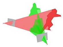
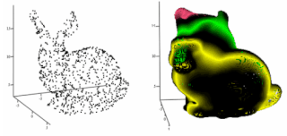
Generating and reconstructing 3D shapes from single or multi-view depth maps or silhouettesA "visual hull" reconstructed from multiple viewpoints
Shape-from-shading Due to the analysis of the shade information in the image, by using Lambertian reflectance, the depth of normal information of the object surface is restored to reconstruct.[12]
Photometric Stereo This approach is more sophisticated than the shape-of-shading method. Images taken in different lighting conditions are used to solve the depth information. It is worth mentioning that more than one image is required by this approach.[13]
Shape-from-texture Suppose such an object with smooth surface covered by replicated texture units, and its projection from 3D to 2D causes distortion and perspective. Distortion and perspective measured in 2D images provide the hint for inversely solving depth of normal information of the object surface.[14]
Machine Learning Based Solutions Machine learning enables learning the correspondance between the subtle features in the input and the respective 3D equivalent. Deep neural networks have shown to be highly effective for 3D reconstruction from a single color image. [15] This works even for non-photorealistic input images such as sketches. [16] Thanks to the high level of accuracy in the reconstructed 3D features, deep learning based method has been employed for biomedical engineering applications to reconstruct CT imagery from X-ray. [17]
Stereo vision obtains the 3-dimensional geometric information of an object from multiple images based on the research of human visual system.[18] The results are presented in form of depth maps. Images of an object acquired by two cameras simultaneously in different viewing angles, or by one single camera at different time in different viewing angles, are used to restore its 3D geometric information and reconstruct its 3D profile and location. This is more direct than Monocular methods such as shape-from-shading.
Binocular stereo vision method requires two identical cameras with parallel optical axis to observe one same object, acquiring two images from different points of view. In terms of trigonometry relations, depth information can be calculated from disparity. Binocular stereo vision method is well developed and stably contributes to favorable 3D reconstruction, leading to a better performance when compared to other 3D construction. Unfortunately, it is computationally intensive, besides it performs rather poorly when baseline distance is large.
Problem statement and basics
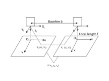
The approach of using Binocular stereo vision to acquire object's 3D geometric information is on the basis of visual disparity.[19] The following picture provides a simple schematic diagram of horizontally sighted Binocular Stereo Vision, where b is the baseline between projective centers of two cameras.
Geometry of a stereoscopic system
The origin of the camera's coordinate system is at the optical center of the camera's lens as shown in the figure. Actually, the camera's image plane is behind the optical center of the camera's lens. However, to simplify the calculation, images are drawn in front of the optical center of the lens by f. The u-axis and v-axis of the image's coordinate system are in the same direction with x-axis and y-axis of the camera's coordinate system respectively. The origin of the image's coordinate system is located on the intersection of imaging plane and the optical axis. Suppose such world point whose corresponding image points are and respectively on the left and right image plane. Assume two cameras are in the same plane, then y-coordinates of and are identical, i.e.,. According to trigonometry relations,
where are coordinates of in the left camera's coordinate system, is focal length of the camera. Visual disparity is defined as the difference in image point location of a certain world point acquired by two cameras,
based on which the coordinates of can be worked out.
Therefore, once the coordinates of image points is known, besides the parameters of two cameras, the 3D coordinate of the point can be determined.
The 3D reconstruction consists of the following sections:
Image acquisition
2D digital image acquisition is the information source of 3D reconstruction. Commonly used 3D reconstruction is based on two or more images, although it may employ only one image in some cases. There are various types of methods for image acquisition that depends on the occasions and purposes of the specific application. Not only the requirements of the application must be met, but also the visual disparity, illumination, performance of camera and the feature of scenario should be considered.
Camera calibration in Binocular Stereo Vision refers to the determination of the mapping relationship between the image points and , and space coordinate in the 3D scenario. Camera calibration is a basic and essential part in 3D reconstruction via Binocular Stereo Vision.
The aim of feature extraction is to gain the characteristics of the images, through which the stereo correspondence processes. As a result, the characteristics of the images closely link to the choice of matching methods. There is no such universally applicable theory for features extraction, leading to a great diversity of stereo correspondence in Binocular Stereo Vision research.
Stereo correspondence is to establish the correspondence between primitive factors in images, i.e. to match and from two images. Certain interference factors in the scenario should be noticed, e.g. illumination, noise, surface physical characteristic, etc.
Restoration
According to precise correspondence, combined with camera location parameters, 3D geometric information can be recovered without difficulties. Due to the fact that accuracy of 3D reconstruction depends on the precision of correspondence, error of camera location parameters and so on, the previous procedures must be done carefully to achieve relatively accurate 3D reconstruction.
3D Reconstruction of medical images
Clinical routine of diagnosis, patient follow-up, computer assisted surgery, surgical planning etc. are facilitated by accurate 3D models of the desired part of human anatomy. Main motivation behind 3D reconstruction includes
Improved accuracy due to multi view aggregation.
Detailed surface estimates.
Can be used to plan, simulate, guide, or otherwise assist a surgeon in performing a medical procedure.
The precise position and orientation of the patient's anatomy can be determined.
Helps in a number of clinical areas, such as radiotherapy planning and treatment verification, spinal surgery, hip replacement, neurointerventions and aortic stenting.
Applications:
3D reconstruction has applications in many fields. They include:
Mostly algorithms available for 3D reconstruction are extremely slow and cannot be used in real-time. Though the algorithms presented are still in infancy but they have the potential for fast computation.
Delaunay method involves extraction of tetrahedron surfaces from initial point cloud. The idea of ‘shape’ for a set of points in space is given by concept of alpha-shapes. Given a finite point set S, and the real parameter alpha, the alpha-shape of S is a polytope (the generalization to any dimension of a two dimensional polygon and a three-dimensional polyhedron) which is neither convex nor necessarily connected.[33] For a large value, the alpha-shape is identical to the convex-hull of S. The algorithm proposed by Edelsbrunner and Mucke[34] eliminates all tetrahedrons which are delimited by a surrounding sphere smaller than α. The surface is then obtained with the external triangles from the resulting tetrahedron.[34]
Another algorithm called Tight Cocone[35] labels the initial tetrahedrons as interior and exterior. The triangles found in and out generate the resulting surface.
Both methods have been recently extended for reconstructing point clouds with noise.[35] In this method the quality of points determines the feasibility of the method. For precise triangulation since we are using the whole point cloud set, the points on the surface with the error above the threshold will be explicitly represented on reconstructed geometry.[33]
Marching Cubes
Zero set Methods
Reconstruction of the surface is performed using a distance function which assigns to each point in the space a signed distance to the surface S. A contour algorithm is used to extracting a zero-set which is used to obtain polygonal representation of the object. Thus, the problem of reconstructing a surface from a disorganized point cloud is reduced to the definition of the appropriate function f with a zero value for the sampled points and different to zero value for the rest. An algorithm called marching cubes established the use of such methods.[36] There are different variants for given algorithm, some use a discrete function f, while other use a polyharmonic radial basis function is used to adjust the initial point set.[37][38] Functions like Moving Least Squares, basic functions with local support,[39] based on the Poisson equation have also been used. Loss of the geometry precision in areas with extreme curvature, i.e., corners, edges is one of the main issues encountered. Furthermore, pretreatment of information, by applying some kind of filtering technique, also affects the definition of the corners by softening them. There are several studies related to post-processing techniques used in the reconstruction for the detection and refinement of corners but these methods increase the complexity of the solution.[40]
Solid geometry with volume rendering Image courtesy of Patrick Chris Fragile Ph.D., UC Santa Barbara
VR Technique
Entire volume transparence of the object is visualized using VR technique. Images will be performed by projecting rays through volume data. Along each ray, opacity and color need to be calculated at every voxel. Then information calculated along each ray will to be aggregated to a pixel on image plane. This technique helps us to see comprehensively an entire compact structure of the object. Since the technique needs enormous amount of calculations, which requires strong configuration computers is appropriate for low contrast data. Two main methods for rays projecting can be considered as follows:
Object-order method: Projecting rays go through volume from back to front (from volume to image plane).
Image-order or ray-casting method: Projecting rays go through volume from front to back (from image plane to volume).There exists some other methods to composite image, appropriate methods depending on the user's purposes. Some usual methods in medical image are MIP (maximum intensity projection), MinIP (minimum intensity projection), AC (alpha compositing) and NPVR (non-photorealistic volume rendering).
Tracing a ray through a voxel grid. The voxels which are traversed in addition to those selected using a standard 8-connected algorithm are shown hatched.
Voxel Grid
In this filtering technique input space is sampled using a grid of 3D voxels to reduce the number of points.[41] For each voxel, a centroid is chosen as the representative of all points. There are two approaches, the selection of the voxel centroid or select the centroid of the points lying within the voxel. To obtain internal points average has a higher computational cost, but offers better results. Thus, a subset of the input space is obtained that roughly represents the underlying surface. The Voxel Grid method presents the same problems as other filtering techniques: impossibility of defining the final number of points that represent the surface, geometric information loss due to the reduction of the points inside a voxel and sensitivity to noisy input spaces.
Texture mapping is a method for mapping a texture on a computer-generated graphic. "Texture" in this context can be high frequency detail, surface texture, or color.
Stereoscopy is a technique for creating or enhancing the illusion of depth in an image by means of stereopsis for binocular vision. The word stereoscopy derives from Greek στερεός (stereos) 'firm, solid' and σκοπέω (skopeō) 'to look, to see'. Any stereoscopic image is called a stereogram. Originally, stereogram referred to a pair of stereo images which could be viewed using a stereoscope.
A 3D projection is a design technique used to display a three-dimensional (3D) object on a two-dimensional (2D) surface. These projections rely on visual perspective and aspect analysis to project a complex object for viewing capability on a simpler plane.
An autostereogram is a two-dimensional (2D) image that can create the optical illusion of a three-dimensional (3D) scene. Autostereograms use only one image to accomplish the effect while normal stereograms require two. The 3D scene in an autostereogram is often unrecognizable until it is viewed properly, unlike typical stereograms. Viewing any kind of stereogram properly may cause the viewer to experience vergence-accommodation conflict.
A light field, or lightfield, is a vector function that describes the amount of light flowing in every direction through every point in a space. The space of all possible light rays is given by the five-dimensional plenoptic function, and the magnitude of each ray is given by its radiance. Michael Faraday was the first to propose that light should be interpreted as a field, much like the magnetic fields on which he had been working. The term light field was coined by Andrey Gershun in a classic 1936 paper on the radiometric properties of light in three-dimensional space.
Geometry processing is an area of research that uses concepts from applied mathematics, computer science and engineering to design efficient algorithms for the acquisition, reconstruction, analysis, manipulation, simulation and transmission of complex 3D models. As the name implies, many of the concepts, data structures, and algorithms are directly analogous to signal processing and image processing. For example, where image smoothing might convolve an intensity signal with a blur kernel formed using the Laplace operator, geometric smoothing might be achieved by convolving a surface geometry with a blur kernel formed using the Laplace-Beltrami operator.
3D scanning is the process of analyzing a real-world object or environment to collect three dimensional data of its shape and possibly its appearance. The collected data can then be used to construct digital 3D models.
In computer graphics and computer vision, image-based modeling and rendering (IBMR) methods rely on a set of two-dimensional images of a scene to generate a three-dimensional model and then render some novel views of this scene.
In mathematics and its applications, the signed distance function or signed distance field (SDF) is the orthogonal distance of a given point x to the boundary of a set Ω in a metric space, with the sign determined by whether or not x is in the interior of Ω. The function has positive values at points x inside Ω, it decreases in value as x approaches the boundary of Ω where the signed distance function is zero, and it takes negative values outside of Ω. However, the alternative convention is also sometimes taken instead. The concept also sometimes goes by the name oriented distance function/field.
Binocular disparity refers to the difference in image location of an object seen by the left and right eyes, resulting from the eyes' horizontal separation (parallax). The mind uses binocular disparity to extract depth information from the two-dimensional retinal images in stereopsis. In computer vision, binocular disparity refers to the difference in coordinates of similar features within two stereo images.
Image rectification is a transformation process used to project images onto a common image plane. This process has several degrees of freedom and there are many strategies for transforming images to the common plane. Image rectification is used in computer stereo vision to simplify the problem of finding matching points between images, and in geographic information systems (GIS) to merge images taken from multiple perspectives into a common map coordinate system.
Articulated body pose estimation in computer vision is the study of algorithms and systems that recover the pose of an articulated body, which consists of joints and rigid parts using image-based observations. It is one of the longest-lasting problems in computer vision because of the complexity of the models that relate observation with pose, and because of the variety of situations in which it would be useful.
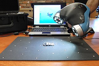
A structured-light 3D scanner is a device that measures the three-dimensional shape of an object by projecting light patterns—such as grids or stripes—onto it and capturing their deformation with cameras. This technique allows for precise surface reconstruction by analyzing the displacement of the projected patterns, which are processed into detailed 3D models using specialized algorithms.
Photometric stereo is a technique in computer vision for estimating the surface normals of objects by observing that object under different lighting conditions (photometry). It is based on the fact that the amount of light reflected by a surface is dependent on the orientation of the surface in relation to the light source and the observer. By measuring the amount of light reflected into a camera, the space of possible surface orientations is limited. Given enough light sources from different angles, the surface orientation may be constrained to a single orientation or even overconstrained.
In computer graphics, hierarchical RBF is an interpolation method based on radial basis functions (RBFs). Hierarchical RBF interpolation has applications in the construction of shape models in 3D computer graphics, treatment of results from a 3D scanner, terrain reconstruction, and others.
Camera auto-calibration is the process of determining internal camera parameters directly from multiple uncalibrated images of unstructured scenes. In contrast to classic camera calibration, auto-calibration does not require any special calibration objects in the scene. In the visual effects industry, camera auto-calibration is often part of the "Match Moving" process where a synthetic camera trajectory and intrinsic projection model are solved to reproject synthetic content into video.
Computer stereo vision is the extraction of 3D information from digital images, such as those obtained by a CCD camera. By comparing information about a scene from two vantage points, 3D information can be extracted by examining the relative positions of objects in the two panels. This is similar to the biological process of stereopsis.
2D to 3D video conversion is the process of transforming 2D ("flat") film to 3D form, which in almost all cases is stereo, so it is the process of creating imagery for each eye from one 2D image.
3D reconstruction from multiple images is the creation of three-dimensional models from a set of images. It is the reverse process of obtaining 2D images from 3D scenes.
Perspective-n-Point is the problem of estimating the pose of a calibrated camera given a set of n 3D points in the world and their corresponding 2D projections in the image. The camera pose consists of 6 degrees-of-freedom (DOF) which are made up of the rotation and 3D translation of the camera with respect to the world. This problem originates from camera calibration and has many applications in computer vision and other areas, including 3D pose estimation, robotics and augmented reality. A commonly used solution to the problem exists for n = 3 called P3P, and many solutions are available for the general case of n ≥ 3. A solution for n = 2 exists if feature orientations are available at the two points. Implementations of these solutions are also available in open source software.
1 2 Liping Zheng; Guangyao Li; Jing Sha (2007). "The survey of medical image 3D reconstruction". In Luo, Qingming; Wang, Lihong V.; Tuchin, Valery V.; Gu, Min (eds.). Fifth International Conference on Photonics and Imaging in Biology and Medicine. Proceedings of SPIE. Vol.6534. pp.65342K–65342K–6. doi:10.1117/12.741321. S2CID62548928.
↑ Moons, Theo (2010). 3D reconstruction from multiple images. Part 1, Principles. Gool, Luc van., Vergauwen, Maarten. Hanover, MA: Now Publishers, Inc. ISBN978-1-60198-285-8. OCLC607557354.
↑ Feng, Qi; Shum, Hubert P. H.; Morishima, Shigeo (2022). "360 Depth Estimation in the Wild - The Depth360 Dataset and the SegFuse Network". 2022 IEEE Conference on Virtual Reality and 3D User Interfaces (VR). IEEE. pp.664–673. arXiv:2202.08010. doi:10.1109/VR51125.2022.00087. ISBN978-1-6654-9617-9.
↑ Thrun, Sebastian. "Robotic mapping: A survey." Exploring artificial intelligence in the new millennium 1.1-35 (2002): 1.
↑ Poullis, Charalambos; You, Suya (May 2011). "3D Reconstruction of Urban Areas". 2011 International Conference on 3D Imaging, Modeling, Processing, Visualization and Transmission. pp.33–40. doi:10.1109/3dimpvt.2011.14. ISBN978-1-61284-429-9. S2CID1189988.
↑ Lorensen, William E.; Cline, Harvey E. (July 1987). "Marching cubes: A high resolution 3D surface construction algorithm". ACM SIGGRAPH Computer Graphics. 21 (4): 163–169. CiteSeerX10.1.1.545.613. doi:10.1145/37402.37422.
↑ Wang, C.L. (June 2006). "Incremental reconstruction of sharp edges on mesh surfaces". Computer-Aided Design. 38 (6): 689–702. doi:10.1016/j.cad.2006.02.009.
↑ Connolly, C. (1984). "Cumulative generation of octree models from range data". Proceedings. 1984 IEEE International Conference on Robotics and Automation. Vol.1. pp.25–32. doi:10.1109/ROBOT.1984.1087212.
This page is based on this Wikipedia article Text is available under the CC BY-SA 4.0 license; additional terms may apply. Images, videos and audio are available under their respective licenses.