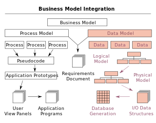
Figure demonstrating the concept of anchor modeling
Anchor modeling is an agiledatabasemodeling technique suited for information that changes over time both in structure and content. It provides a graphical notation used for conceptual modeling similar to that of entity-relationship modeling, with extensions for working with temporal data. The modeling technique involves four modeling constructs: the anchor, attribute, tie and knot, each capturing different aspects of the domain being modeled.[1] The resulting models can be translated to physical database designs using formalized rules. When such a translation is done the tables in the relational database will mostly be in the sixth normal form.
Unlike the star schema (dimensional modelling) and the classical relational model (3NF), data vault and anchor modeling are well-suited for capturing changes that occur when a source system is changed or added, but are considered advanced techniques which require experienced data architects.[2] Both data vaults and anchor models are entity-based models,[3] but anchor models have a more normalized approach.[citation needed]
Philosophy
Anchor modeling was created in order to take advantage of the benefits from a high degree of normalization while avoiding its drawbacks which higher normal forms have with regards to human readability. Advantages such as being able to non-destructively evolve the model, avoid null values, and keep the information free from redundancies are gained. Performance issues due to extra joins are largely avoided thanks to a feature in modern database engines[when?] called join elimination or table elimination. In order to handle changes in the information content, anchor modeling emulates aspects of a temporal database in the resulting relational database schema.
History
The earliest installations using anchor modeling were made 2004 in Sweden when a data warehouse for an insurance company was built using the technique.
In 2007 the technique was being used in a few data warehouses and one online transaction processing (OLTP) system, and it was presented internationally by Lars Rönnbäck at the 2007 Transforming Data with Intelligence (TDWI) conference in Amsterdam.[4] This stirred enough interest for the technique to warrant a more formal description. Since then research concerning anchor modeling is being done in a collaboration between the creators Olle Regardt and Lars Rönnbäck and a team at the Department of Computer and Systems Sciences, Stockholm University.
A commercial web site provides material on anchor modeling which is free to use under a Creative Commons license. An online modeling tool is also available, which is free to use and is open source.[6]
Basic notions
Anchor modeling has four basic modeling concepts: anchors, attributes, ties, and knots. Anchors are used to model entities and events, attributes are used to model properties of anchors, ties model the relationships between anchors, and knots are used to model shared properties, such as states. Attributes and ties can be historized when changes in the information they model need to be kept.
An example model showing the different graphical symbols for all the concepts can be seen below. The symbols resemble those used in entity–relationship modeling, with a couple of extensions. A double outline on an attribute or tie indicates that a history of changes is kept. The knot symbol (an outlined square with rounded edges) is also available, but knots cannot be historized. The anchor symbol is a solid square.
Temporal aspects
Anchor modeling handles two types of informational evolution, which are structural changes and content changes. Changes to the structure of information is represented through extensions. The high degree of normalization makes it possible to non-destructively add the necessary modeling concepts needed to capture a change, in such a way that every previous schema always remains as a subset of the current schema. Since the existing schema is not touched, this gives the benefit of being able to evolve the database in a highly iterative manner and without causing any downtime.
Changes in the content of information is done by emulating similar features of a temporal database in a relational database. In anchor modeling, pieces of information can be tied to points in time or to intervals of time (both open and closed). The time points when events occur are modeled using attributes, e g the birth dates of persons or the time of a purchase. The intervals of time in which a value is valid are captured through the historization of attributes and ties, e g the changes of hair color of a person or the period of time during which a person was married. In a relational database this is achieved by adding a single column, with a data type granular enough to capture the speed of the changes, to the table corresponding to the historized attribute or tie. This adds a slight complexity as more than one row in the table have to be examined in order to know if an interval is closed or not.
Points or intervals of time not directly related to the domain being modeled, such as the points of time information entered the database, are handled through the use of metadata in anchor modeling, rather than any of the above-mentioned constructs. If information about such changes to the database needs to be kept then bitemporal anchor modeling can be used, where in addition to updates, also delete statements become non-destructive.
Relational representation
In anchor modeling there is a one-to-one mapping between the symbols used in the conceptual model and tables in the relational database. Every anchor, attribute, tie, and knot have a corresponding table in the database with an unambiguously defined structure. A conceptual model can thereby be translated to a relational database schema using simple automated rules, and vice versa. This is different from many other modeling techniques in which there are complex and sometimes subjective translation steps between the conceptual, logical, and physical levels.
Anchor tables contain a single column in which identities are stored. An identity is assumed to be the only property of an entity that is always present and immutable. As identities are rarely available from the domain being modeled, they are instead technically generated, e g from an incrementing number sequence.
An example of an anchor for the identities of the nephews of Donald Duck is a set of 1-tuples: {⟨#42⟩, ⟨#43⟩, ⟨#44⟩}
Knots can be thought of as the combination of an anchor and a single attribute. Knot tables contain two columns, one for an identity and one for a value. Due to storing identities and values together, knots cannot be historized. Their usefulness comes from being able to reduce storage requirements and improve performance, since tables referencing knots can store a short value rather than a long string.
An example of a knot for genders is a set of 2-tuples: {⟨#1, 'Male'⟩, ⟨#2, 'Female'⟩}
Static attribute tables contain two columns, one for the identity of the entity to which the value belongs and one for the actual property value. Historized attribute tables have an extra column for storing the starting point of a time interval. In a knotted attribute table, the value column is an identity that references a knot table.
An example of a static attribute for their names is a set of 2-tuples: {⟨#42, 'Huey'⟩, ⟨#43, 'Dewey'⟩, ⟨#44, 'Louie'⟩}
An example of a knotted static attribute for their genders is a set of 2-tuples: {⟨#42, #1⟩, ⟨#43, #1⟩, ⟨#44, #1⟩}
An example of a historized attribute for the (changing) colors of their outfits is a set of 3-tuples: {⟨#44, 'Orange', 1938-04-15⟩, ⟨#44, 'Green', 1939-04-28⟩, ⟨#44, 'Blue', 1940-12-13⟩}
Static tie tables relate two or more anchors to each other, and contain two or more columns for storing the identities. Historized tie tables have an extra column for storing the starting point of a time interval. Knotted tie tables have an additional column for each referenced knot.
An example of a static tie for the sibling relationship is a set of 2-tuples: {⟨#42, #43⟩, ⟨#42, #44⟩, ⟨#43, #42⟩, ⟨#43, #44⟩, ⟨#44, #42⟩, ⟨#44, #43⟩}
The resulting tables will all be in sixth normal form except for ties in which not all columns are part of the primary key.
Compared to other approaches
In the 2000s, several data warehouse data modeling patterns have been introduced with the goal of achieving agile data warehouses, including ensemble modeling forms such as anchor modeling, data vault modeling, focal point modeling, and others.[7]
Data vault comparison
In 2013 at the data modeling conference BI Podium in the Netherlands, Lars Rönnbäck presented a comparison of anchor modeling and data vault modeling.[8]
Any-temporal by hand, end-dating optional (not recommended)
AM
Concurrent-temporal by design, no end-dating
Tightening
Updates may be necessary
AM
Insert only
Tool support
Many tools Mostly commercial
DV
Few tools Only open-source
Adapting to change
Still cumbersome
AM
Almost effortless
Model interchange
Raw SQL with printed diagrams of some flavor
AM
Standardized XML format and graphical notation
Immutability
Surrogate identity and natural key
AM
Only surrogate identity
Natural to surrogate
One-to-one, static Physically realized (hub)
AM
Many-to-one, historizable Logical view over the data
Query optimization
Somewhat important Recent databases
DV
Very important Latest version databases
Scriptability
With some effort
AM
Formalized, automated for everything
Views and triggers
Mentioned, hand-made and case-by-case
AM
Formalized, automated for everything
Assumptions
Built to last Needs assumptions
AM
Built to change No assumptions
Market share
Small <1000 installations (2013)
DV
Very small <100 installations (2013)
Related Research Articles
In computing, a data warehouse, also known as an enterprise data warehouse (EDW), is a system used for reporting and data analysis and is considered a core component of business intelligence. Data warehouses are central repositories of integrated data from one or more disparate sources. They store current and historical data in one single place that are used for creating reports. This is beneficial for companies as it enables them to interrogate and draw insights from their data and make decisions.
In computing, a database is an organized collection of data or a type of data store based on the use of a database management system (DBMS), the software that interacts with end users, applications, and the database itself to capture and analyze the data. The DBMS additionally encompasses the core facilities provided to administer the database. The sum total of the database, the DBMS and the associated applications can be referred to as a database system. Often the term "database" is also used loosely to refer to any of the DBMS, the database system or an application associated with the database.
A relational database (RDB) is a database based on the relational model of data, as proposed by E. F. Codd in 1970. A database management system used to maintain relational databases is a relational database management system (RDBMS). Many relational database systems are equipped with the option of using SQL for querying and updating the database.
The relational model (RM) is an approach to managing data using a structure and language consistent with first-order predicate logic, first described in 1969 by English computer scientist Edgar F. Codd, where all data is represented in terms of tuples, grouped into relations. A database organized in terms of the relational model is a relational database.
A data model is an abstract model that organizes elements of data and standardizes how they relate to one another and to the properties of real-world entities. For instance, a data model may specify that the data element representing a car be composed of a number of other elements which, in turn, represent the color and size of the car and define its owner.
Tuple calculus is a calculus that was created and introduced by Edgar F. Codd as part of the relational model, in order to provide a declarative database-query language for data manipulation in this data model. It formed the inspiration for the database-query languages QUEL and SQL, of which the latter, although far less faithful to the original relational model and calculus, is now the de facto standard database-query language; a dialect of SQL is used by nearly every relational-database-management system. Michel Lacroix and Alain Pirotte proposed domain calculus, which is closer to first-order logic and together with Codd showed that both of these calculi are equivalent in expressive power. Subsequently, query languages for the relational model were called relationally complete if they could express at least all of these queries.
Referential integrity is a property of data stating that all its references are valid. In the context of relational databases, it requires that if a value of one attribute (column) of a relation (table) references a value of another attribute, then the referenced value must exist.
An entity–relationship model describes interrelated things of interest in a specific domain of knowledge. A basic ER model is composed of entity types and specifies relationships that can exist between entities.
Data modeling in software engineering is the process of creating a data model for an information system by applying certain formal techniques. It may be applied as part of broader Model-driven engineering (MDE) concept.
Database design is the organization of data according to a database model. The designer determines what data must be stored and how the data elements interrelate. With this information, they can begin to fit the data to the database model. A database management system manages the data accordingly.
In a database, a table is a collection of related data organized in table format; consisting of columns and rows.
Object–relational impedance mismatch is a set of difficulties going between data in relational data stores and data in domain-driven object models. Relational Database Management Systems (RDBMS) is the standard method for storing data in a dedicated database, while object-oriented (OO) programming is the default method for business-centric design in programming languages. The problem lies in neither relational databases nor OO programming, but in the conceptual difficulty mapping between the two logic models. Both logical models are differently implementable using database servers, programming languages, design patterns, or other technologies. Issues range from application to enterprise scale, whenever stored relational data is used in domain-driven object models, and vice versa. Object-oriented data stores can trade this problem for other implementation difficulties.
Integration DEFinition for information modeling (IDEF1X) is a data modeling language for the development of semantic data models. IDEF1X is used to produce a graphical information model which represents the structure and semantics of information within an environment or system.
An entity–attribute–value model (EAV) is a data model optimized for the space-efficient storage of sparse—or ad-hoc—property or data values, intended for situations where runtime usage patterns are arbitrary, subject to user variation, or otherwise unforeseeable using a fixed design. The use-case targets applications which offer a large or rich system of defined property types, which are in turn appropriate to a wide set of entities, but where typically only a small, specific selection of these are instantiated for a given entity. Therefore, this type of data model relates to the mathematical notion of a sparse matrix. EAV is also known as object–attribute–value model, vertical database model, and open schema.
In relational database management systems, a unique key is a candidate key. All the candidate keys of a relation can uniquely identify the records of the relation, but only one of them is used as the primary key of the relation. The remaining candidate keys are called unique keys because they can uniquely identify a record in a relation. Unique keys can consist of multiple columns. Unique keys are also called alternate keys. Unique keys are an alternative to the primary key of the relation. In SQL, the unique keys have a UNIQUE constraint assigned to them in order to prevent duplicates. Alternate keys may be used like the primary key when doing a single-table select or when filtering in a where clause, but are not typically used to join multiple tables.
A database model is a type of data model that determines the logical structure of a database. It fundamentally determines in which manner data can be stored, organized and manipulated. The most popular example of a database model is the relational model, which uses a table-based format.
In database theory, a relation, as originally defined by E. F. Codd, is a set of tuples (d1,d2,...,dn), where each element dj is a member of Dj, a data domain. Codd's original definition notwithstanding, and contrary to the usual definition in mathematics, there is no ordering to the elements of the tuples of a relation. Instead, each element is termed an attribute value. An attribute is a name paired with a domain. An attribute value is an attribute name paired with an element of that attribute's domain, and a tuple is a set of attribute values in which no two distinct elements have the same name. Thus, in some accounts, a tuple is described as a function, mapping names to values.
Knowledge extraction is the creation of knowledge from structured and unstructured sources. The resulting knowledge needs to be in a machine-readable and machine-interpretable format and must represent knowledge in a manner that facilitates inferencing. Although it is methodically similar to information extraction (NLP) and ETL, the main criterion is that the extraction result goes beyond the creation of structured information or the transformation into a relational schema. It requires either the reuse of existing formal knowledge or the generation of a schema based on the source data.
The standard column family is a NoSQL object that contains columns of related data. It is a tuple (pair) that consists of a key–value pair, where the key is mapped to a value that is a set of columns. In analogy with relational databases, a standard column family is as a "table", each key–value pair being a "row". Each column is a tuple consisting of a column name, a value, and a timestamp. In a relational database table, this data would be grouped together within a table with other non-related data.
The following is provided as an overview of and topical guide to databases:
References
↑ L. Rönnbäck; O. Regardt; M. Bergholtz; P. Johannesson; P. Wohed (2010). "Anchor modeling - Agile information modeling in evolving data environments". Data & Knowledge Engineering. 69 (12): 1229–1253. doi:10.1016/j.datak.2010.10.002. ISSN0169-023X. (Preprint available here)
This page is based on this Wikipedia article Text is available under the CC BY-SA 4.0 license; additional terms may apply. Images, videos and audio are available under their respective licenses.