Antenna measurement techniques refer to the testing of antennas to ensure that they meet specifications or simply to characterize them. Typical antenna parameters include gain, bandwidth, radiation pattern, beamwidth, polarization, and impedance. These parameters are essential for effective communication.
The antenna pattern is the response of the antenna to a plane wave incident from a given direction or the relative power density of the wave transmitted by the antenna in a given direction. For a reciprocal antenna, these two patterns are identical. A multitude of antenna pattern measurement techniques have been developed. The first technique developed was the far-field range, where the antenna under test (AUT) is placed in the far-field of a range antenna. Due to the size required to create a far-field range for large antennas, near-field techniques were developed, which allow the measurement of the field on a distance close to the antenna (typically 3 to 10 times its wavelength). This measurement is then predicted to be the same at infinity. A third common method is the compact range, which uses a reflector to create a field near the AUT that looks approximately like a plane-wave.
Far-field range (FF)
The far-field range was the original antenna measurement technique, and the simplest; it consists of placing the antenna under test (AUT) a long distance away from the instrumentation antenna. Generally, the far-field distance or Fraunhofer distance, is considered to be
where is the widest diameter of the antenna in any direction, and is the wavelength of the radio wave.[1] Separating the AUT and the standard receiving antenna by this distance reduces the detectable phase variation across the AUT enough to obtain a reasonably accurate estimate of the antenna pattern in the far distance.
The IEEE antenna measurement standard (document i.d. IEEE-Std-149-1979), suggests set-up for measurement and various techniques for both far-field ranges and ground-bounce ranges (discussed below).
Planar near-field measurements are conducted by scanning a small probe antenna over a planar surface. These measurements are then transformed to the far-field by use of a Fourier transform, or more specifically by applying a method known as stationary phase[2] to the Laplace transform . Three basic types of planar scans exist in near field measurements.
Rectangular planar scanning
The probe moves in the Cartesian coordinate system and its linear movement creates a regular rectangular sampling grid with a maximum near-field sample spacing of Δx = Δy = λ /2.
Polar planar scanning
More complicated solution to the rectangular scanning method is the plane polar scanning method.
Bi-polar planar scanning
The bi-polar technique is very similar to the plane polar configuration.
Cylindrical near-field range
Cylindrical near-field ranges measure the electric field on a cylindrical surface close to the AUT. Cylindrical harmonics are used transform these measurements to the far-field.
Spherical near-field range
Spherical near-field ranges measure the electric field on a spherical surface close to the AUT. Spherical harmonics are used transform these measurements to the far-field
Free-space ranges
This section needs expansion. You can help by adding to it. (June 2008)
The formula for electromagnetic radiation dispersion and information propagation is:
where D represents distance, P power and S speed.
The equation means that double the communication distance requires four times the power. It also means double power allows double communication speed (bit rate). Double power is approximately 3dB increase (or exactly 10×log10(2) ≈ 3.0103000). Of course, in the real world there are all sorts of other phenomena which complicate the estimated delivered power, such as Fresnel canceling, path loss, background noise, etc.
Compact range
A Compact Antenna Test Range (CATR) is a facility which is used to provide convenient testing of antenna systems at frequencies where obtaining far-field spacing to the AUT would be infeasible using traditional free space methods. It was invented by Richard C. Johnson at the Georgia Tech Research Institute.[3] The CATR uses a source antenna which radiates a spherical wavefront and one or more secondary reflectors to collimate the radiated spherical wavefront into a planar wavefront within the desired test zone. One typical embodiment uses a horn feed antenna and a parabolic reflector to accomplish this.
The CATR is used for microwave and millimeter wave frequencies where the far-field distance is large, such as with high-gain reflector antennas. The size of the range that is required can be much less than the size required for a full-size far-field anechoic chamber, although the cost of fabrication of the specially designed CATR reflector can be expensive due to the need to ensure precision of the reflecting surface (typically less than 1/100λRMS surface accuracy) and to specially treat the edge of the reflector to avoid diffracted waves which can interfere with the desired beam pattern.
Elevated range
In an elevated range, the AUT and the measuring antenna are both mounted several wavelengths above ground leveal as a means of reducing the interference from waves reflected off the ground.
Slant range
In a slanted range, the receive antenna is mounted higher above ground than the AUT is, either by having the earth surface of the range sloping downward from the AUT mount, or by placing the receive antenna on a much higher mast. The sloping earth (either actual or effective) serves as a means to eliminate or reduce interference from symmetrical wave reflection, by angling the reflected waves to bounce underneath the receive antenna. In theory, the same technique could be applied in reverse, to bounce most of the earth-reflected waves above the receive antenna.
Except for polarization, the SWR is the most easily measured of the parameters above. Impedance can be measured with specialized equipment, as it relates to the complex SWR. Measuring radiation pattern requires a sophisticated setup including significant clear space (enough to put the sensor into the antenna's far field, or an anechoic chamber designed for antenna measurements), careful study of experiment geometry, and specialized measurement equipment that rotates the antenna during the measurements.
The radiation pattern is a graphical depiction of the relative field strength transmitted from or received by the antenna. Apart from the mainlobe, it shows sidelobes and backlobes. As antennas radiate in space often several curves are necessary to describe the antenna. If the radiation of the antenna is symmetrical about an axis (as is the case in dipole, helical and some parabolic antennas) a unique graph is sufficient.
Each antenna supplier/user has different standards as well as plotting formats. Each format has its own advantages and disadvantages. Radiation pattern of an antenna can be defined as the locus of all points where the emitted power per unit surface is the same. The radiated power per unit surface is proportional to the squared electrical field of the electromagnetic wave. The radiation pattern is the locus of points with the same electrical field. In this representation, the reference is usually the best angle of emission. It is also possible to depict the directive gain of the antenna as a function of the direction. Often the gain is given in decibels.
The graphs can be drawn using Cartesian (rectangular) coordinates or a polar plot. This last one is useful to measure the beamwidth, which is, by convention, the angle at the −3dB points around the max gain. The shape of curves can be very different in Cartesian or polar coordinates and with the choice of the limits of the logarithmic scale. The four drawings below are the radiation patterns of a same half-wave antenna.
Radiation pattern of a half-wave dipole antenna. Linear scale.
Gain of a half-wave dipole. The scale is in dBi.
Gain of a half-wave dipole. Cartesian representation.
3D radiation pattern of a half-wave dipole antenna.
Efficiency is the ratio of power actually radiated by an antenna to the electrical power it receives from a transmitter. A dummy load may have an SWR of 1:1 but an efficiency of 0, as it absorbs all the incident power, producing heat but radiating no RF energy; SWR is not a measure of an antenna's efficiency. Radiation resistance is the part of the resistance to current caused by power lost to radiation by an antenna. Unfortunately, it cannot be directly measured but is a component of the total resistance which includes the loss resistance. Loss resistance is the result of power lost to heat in the antenna materials, rather than to coherent radio waves, thus reducing efficiency.
Efficiency () is defined as the ratio of the power coherently radiated as radio waves () to the total power used by the antenna, which is the sum of the power radiated coherently () and the power radiated as heat ():
The antenna efficiency is also mathematically equal to the radiation resistance () divided by total resistance (real part of the impedance measured at the voltage node, which is often the feed-point):
IEEE defines bandwidth as "The range of frequencies within which the performance of the antenna, with respect to some characteristic, conforms to a specified standard."[4] In other words, bandwidth depends on the overall effectiveness of the antenna through a range of frequencies, so all of these parameters must be understood to fully characterize the bandwidth capabilities of an antenna. This definition may serve as a practical definition, however, in practice, bandwidth is typically determined by measuring a characteristic such as SWR or radiated power over the frequency range of interest. For example, the SWR bandwidth is typically determined by measuring the frequency range where the SWR is less than 2:1. Another frequently used value for determining bandwidth for resonant antennas is the −3 dB return loss value, since loss due to SWR is −10·log10(2÷1) = −3.01000 dB.
Antenna directivity is the ratio of maximum radiation intensity (power per unit surface) radiated by the antenna in the maximum direction divided by the intensity radiated by a hypothetical isotropic antenna radiating the same total power as that antenna. For example, a hypothetical antenna which had a radiated pattern of a hemisphere (1/2 sphere) would have a directivity of 2. Directivity is a dimensionless ratio and may be expressed numerically or in decibels (dB). Directivity is identical to the peak value of the directive gain; these values are specified without respect to antenna efficiency thus differing from the power gain (or simply "gain") whose value is reduced by an antenna's efficiency.
Gain as a parameter measures the directionality of a given antenna. An antenna with a low gain emits radiation in all directions equally, whereas a high-gain antenna will preferentially radiate in particular directions. Specifically, the Gain or Power gain of an antenna is defined as the ratio of the intensity (power per unit surface) radiated by the antenna in a given direction at an arbitrary distance divided by the intensity radiated at the same distance by an hypothetical isotropic antenna:
We write "hypothetical" because a perfect isotropic antenna cannot be constructed. Gain is a dimensionless number (without units).
The gain of an antenna is a passive phenomenon - power is not added by the antenna, but simply redistributed to provide more radiated power in a certain direction than would be transmitted by an isotropic antenna. If an antenna has a greater than one gain in some directions, it must have a less than one gain in other directions since energy is conserved by the antenna. An antenna designer must take into account the application for the antenna when determining the gain. High-gain antennas have the advantage of longer range and better signal quality, but must be aimed carefully in a particular direction. Low-gain antennas have shorter range, but the orientation of the antenna is inconsequential. For example, a dish antenna on a spacecraft is a high-gain device (must be pointed at the planet to be effective), while a typical WiFi antenna in a laptop computer is low-gain (as long as the base station is within range, the antenna can be in an any orientation in space).
Physical background
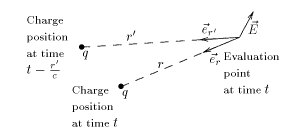
The measured electrical field was radiated seconds earlier.
is the distance from the observation point (the place where is evaluated) to the point where the charge was seconds before the time when the measure is done.
is the unit vector directed from the observation point (the place where is evaluated) to the point where the charge was seconds before the time when the measure is done.
The "prime" in this formula appears because the electromagnetic signal travels at the speed of light. Signals are observed as coming from the point where they were emitted and not from the point where the emitter is at the time of observation. The stars that we see in the sky are no longer where we see them. We will see their current position years in the future; some of the stars that we see today no longer exist.
The first term in the formula is just the electrostatic field with retarded time. The second term is as though nature were trying to allow for the fact that the effect is retarded (Feynman). These two terms describe the near field of an antenna.The third term is the term that accounts for the far field of antennas. Its second derivative describes the acceleration of the charge q. Only accelerated charged particles emit electromagnetic radiation. The first two terms are proportional to . Only the third is proportional to .
Near the antenna, all the terms are important. However, if the distance is large enough, the first two terms become negligible and only the third remains:
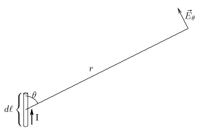
Electrical field radiated by an element of current. The element of current, the electrical field vector and are on the same plane.
If the charge q is in sinusoidal motion, meaning that it is being accelerated, with amplitude and pulsation the power radiated by the charge is:
watts.
Note that the radiated power is proportional to the fourth power of the frequency. It is far easier to radiate at high frequencies than at low frequencies. If the motion of charges is due to currents, it can be shown that the (small) electrical field radiated by a small length of a conductor carrying a time varying current is
The left side of this equation is the electrical field of the electromagnetic wave radiated by a small length of conductor. The index reminds that the field is perpendicular to the line to the source. The reminds that this is the field observed seconds after the evaluation on the current derivative. The angle is the angle between the direction of the current and the direction to the point where the field is measured.
The electrical field and the radiated power are maximal in the plane perpendicular to the current element. They are zero in the direction of the current.
Only time-varying currents radiate electromagnetic power.
If the current is sinusoidal, it can be written in complex form, in the same way used for impedances. Only the real part is physically meaningful:
where:
is the amplitude of the current.
is the angular frequency.
The (small) electric field of the electromagnetic wave radiated by an element of current is:
And for the time :
The electric field of the electromagnetic wave radiated by an antenna formed by wires is the sum of all the electric fields radiated by all the small elements of current. This addition is complicated by the fact that the direction and phase of each of the electric fields are, in general, different.
Calculation of antenna parameters in reception
The gain in any given direction and the impedance at a given frequency are the same when the antenna is used in transmission or in reception.
The electric field of an electromagnetic wave induces a small voltage in each small segment in all electric conductors. The induced voltage depends on the electrical field and the conductor length. The voltage depends also on the relative orientation of the segment and the electrical field.
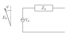
Each small voltage induces a current and these currents circulate through a small part of the antenna impedance. The result of all those currents and tensions is far from immediate. However, using the reciprocity theorem, it is possible to prove that the Thévenin equivalent circuit of a receiving antenna is:
Equivalent circuit of a receiving antenna.
is the Thévenin equivalent circuit tension.
is the Thévenin equivalent circuit impedance and is the same as the antenna impedance.
is the series resistive part of the antenna impedance .
is the directive gain of the antenna (the same as in emission) in the direction of arrival of electromagnetic waves.
is the wavelength.
is the magnitude of the electrical field of the incoming electromagnetic wave.
is the angle of misalignment of the electrical field of the incoming wave with the antenna. For a dipole antenna, the maximum induced voltage is obtained when the electrical field is parallel to the dipole. If this is not the case and they are misaligned by an angle , the induced voltage will be multiplied by .
is a universal constant called vacuum impedance or impedance of free space.
From this formula, it is easy to prove the following definitions:
Antenna effective length
is the length which, multiplied by the electrical field of the received wave, give the voltage of the Thévenin equivalent antenna circuit.
Maximum available power
is the maximum power that an antenna can extract from the incoming electromagnetic wave.
Cross section or effective capture surface
is the surface which multiplied by the power per unit surface of the incoming wave, gives the maximum available power.
The maximum power that an antenna can extract from the electromagnetic field depends only on the gain of the antenna and the squared wavelength . It does not depend on the antenna dimensions.
Using the equivalent circuit, it can be shown that the maximum power is absorbed by the antenna when it is terminated with a load matched to the antenna input impedance. This also implies that under matched conditions, the amount of power re-radiated by the receiving antenna is equal to that absorbed.
Brown, F. W. (November 1964). "How to Measure Antenna Gain". CQ. p.40.
This page is based on this Wikipedia article Text is available under the CC BY-SA 4.0 license; additional terms may apply. Images, videos and audio are available under their respective licenses.