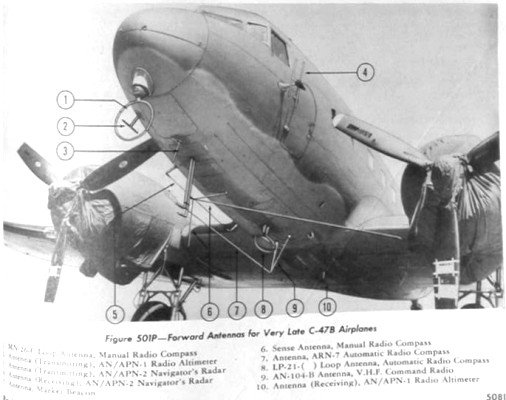
A teardrop-shaped housing that encases LP-21 rotatable loop antenna attached to the underside of Douglas DC-3 "Flagship Knoxville". The loop antenna is used for the ADF.
An automatic direction finder (ADF) is a marine or aircraft radio-navigation instrument that automatically and continuously displays the relative bearing from the ship or aircraft to a suitable radio station.[3][4] ADF receivers are normally tuned to aviation or marine NDBs (Non-Directional Beacon) operating in the longwave band (LW) between 190 – 535kHz. Like RDF (Radio Direction Finder) units, most ADF receivers can also receive medium wave (AM) broadcast stations, though these are less reliable for navigational purposes.
The operator tunes the ADF receiver to the correct frequency and verifies the identity of the beacon by listening to the Morse code signal transmitted by the NDB.[5] On marine ADF receivers, the motorized ferrite-bar antenna atop the unit (or remotely mounted on the masthead) would rotate and lock when reaching the null of the desired station. A centerline on the antenna unit moving atop a compass rose indicated in degrees the bearing of the station. On aviation ADFs, the unit automatically moves a compass-like pointer (RMI) to show the direction of the beacon. The pilot may use this pointer to home directly towards the beacon, or may also use the magnetic compass and calculate the direction from the beacon (the radial) at which their aircraft is located.
Unlike the RDF, the ADF operates without direct intervention, and continuously displays the direction of the tuned beacon. Initially, all ADF receivers, both marine and aircraft versions, contained a rotating loop or ferrite loopstick aerial driven by a motor which was controlled by the receiver. Like the RDF, a sense antenna verified the correct direction from its 180-degree opposite.
More modern aviation ADFs contain a small array of fixed aerials and use electronic sensors to deduce the direction using the strength and phase of the signals from each aerial. The electronic sensors listen for the trough that occurs when the antenna is at right angles to the signal, and provide the heading to the station using a direction indicator. In flight, the ADF's RMI or direction indicator will always point to the broadcast station regardless of aircraft heading. Dip error is introduced, however, when the aircraft is in a banked attitude, as the needle dips down in the direction of the turn. This is the result of the loop itself banking with the aircraft and therefore being at a different angle to the beacon. For ease of visualisation, it can be useful to consider a 90° banked turn, with the wings vertical. The bearing of the beacon as seen from the ADF aerial will now be unrelated to the direction of the aircraft to the beacon.
Dip error is sometimes confused with quadrantal error, which is the result of radio waves being bounced and reradiated by the airframe. Quadrantal error does not affect signals from straight ahead or behind, nor on the wingtips. The further from these cardinal points and the closer to the quadrantal points (i.e. 45°, 135°, 225° and 315° from the nose) the greater the effect, but quadrantal error is normally much less than dip error, which is always present when the aircraft is banked.
ADF receivers can be used to determine current position, track inbound and outbound flight path, and intercept a desired bearing. These procedures are also used to execute holding patterns and non-precision instrument approaches.
Typical service ranges of non-directional beacons (NDBs)
Non-directional beacons in North America are classified by power output: "low" power rating is less than 50 watts; "medium" from 50 W to 2,000 W; and "high" at more than 2,000 W.[6]
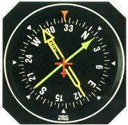
An ADF indicator with a fixed azimuth dial. The airplane is flying a 40° magnetic heading, while the station is 310° relative to the plane (called "relative bearing"). The magnetic bearing to the station in this case is 350°.
The ADF indicators are a kind of navigational display consisting of a dial and a needle that rotates around the dial and points to the beacon. This needle suggests the "to" bearing of the beacon, and to fly the "from" bearing, 180° needs to be added or subtracted from the reading.[7]
There are two types of ADF indicators: the "fixed azimuth dial" type with 0° always represents the aircraft nose, and 180° always represents the aircraft tail; and the type with rotating dials that can be rotated to align the azimuth with the aircraft heading.[7]
Stages
Station passage
As an aircraft nears an NDB station, the ADF becomes increasingly sensitive, small lateral deviations result in large deflections of the needle which sometimes shows erratic left/right oscillations.[8] Ideally, as the aircraft overflies the beacon, the needle swings rapidly from directly ahead to directly behind. This indicates station passage and provides an accurate position fix for the navigator. Less accurate station passage, passing slightly to one side or another, is shown by slower (but still rapid) swinging of the needle. The time interval from the first indications of station proximity to positive station passage varies with altitude — a few moments at low levels to several minutes at high altitude.
Homing
The ADF may be used to home in on a station. Homing is flying the aircraft on the heading required to keep the needle pointing directly to the 0° (straight ahead) position. To home into a station, tune the station, identify the Morse code signal, then turn the aircraft to bring the ADF azimuth needle to the 0° position. Turn to keep the ADF heading indicator pointing directly ahead. Homing is regarded as poor piloting technique because the aircraft may be blown significantly or dangerously off-course by a cross-wind, and will have to fly further and for longer than the direct track.
Tracking
The ADF may also be used to track a desired course using an ADF and allowing for winds aloft, winds which may blow the aircraft off-course. Good pilotage technique has the pilot calculate a correction angle that exactly balances the expected crosswind. As the flight progresses, the pilot monitors the direction to or from the NDB using the ADF, adjusts the correction as required. A direct track will yield the shortest distance and time to the ADF location.[7]
Radio magnetic indicator (RMI)
An aircraft RMI
A radio magnetic indicator (RMI) is an alternate ADF display providing more information than a standard ADF. While the ADF shows relative angle of the transmitter with respect to the aircraft, an RMI display incorporates a compass card, actuated by the aircraft's compass system, and permits the operator to read the magnetic bearing to or from the transmitting station, without resorting to arithmetic.
Most RMIs incorporate two direction needles. Often one needle (the thicker, double-barred needle) is connected to an ADF and the other (generally thin or single-barred) is connected to a VOR. Some models allow the operator to select which needle is connected to each navigation radio. There is great variation between models, and the operator must take care that their selection displays information from the appropriate ADF and VOR.
This instrument display can replace a magnetic compass display in the instrument panel, but not necessarily the gyroscopic Heading Indicator. The Heading Indicator can be combined with information from navigation radios (primarily VOR/ILS) in a similar way, to create the Horizontal Situation Indicator. The HSI, along with the VOR system, has largely replaced use of the RMI, however the HSI's much higher cost keeps the older combination of an RMI and an Omni Bearing Indicator attractive to cost-conscious pilots and operators.
Decline in use
While ADF receivers were once a standard feature in most commercial and general aviation aircraft, their use has declined with the growth of satellite-based navigation systems such as GPS and the implementation of Performance-Based Navigation (PBN). Many civil aviation authorities have gradually decommissioned non-directional beacons (NDBs), particularly in North America and Europe, where more precise navigation aids and satellite augmentation systems are available. Today, ADF equipment is primarily retained for legacy procedures, training purposes, and as a backup in areas with limited satellite coverage.[9]
This page is based on this Wikipedia article Text is available under the CC BY-SA 4.0 license; additional terms may apply. Images, videos and audio are available under their respective licenses.

