Heading indicator

Last updated
A heading indicator in a small aircraft. C172 heading indicator.jpg
A heading indicator in a small aircraft.
HI interior DG interior.png
HI interior
Vacuum Pump system.png
Venturi vacuum.png
Vacuum systems using a vacuum pump (left) and a venturi (right)

The heading indicator (HI), also known as a directional gyro [1] (DG) or direction indicator (DI), [2] [3] [4] [5] is a flight instrument used in an aircraft to inform the pilot of the aircraft's heading.

Contents

Use

The primary means of establishing the heading in most small aircraft is the magnetic compass, which, however, suffers from several types of errors, including that created by the "dip" or downward slope of the Earth's magnetic field. Dip error causes the magnetic compass to read incorrectly whenever the aircraft is in a bank, or during acceleration or deceleration, making it difficult to use in any flight condition other than unaccelerated, perfectly straight and level. To remedy this, the pilot will typically maneuver the airplane with reference to the heading indicator, as the gyroscopic heading indicator is unaffected by dip and acceleration errors. The pilot will periodically reset the heading indicator to the heading shown on the magnetic compass. [4] [6] [7] [8]

Operation

The heading indicator works using a gyroscope, tied by an erection mechanism to the aircraft yawing plane, i. e. the plane defined by the longitudinal and the horizontal axis of the aircraft. As such, any configuration of the aircraft yawing plane that does not match the local Earth horizontal results in an indication error. The heading indicator is arranged such that the gyro axis is used to drive the display, which consists of a circular compass card calibrated in degrees. The gyroscope is spun either electrically, or using filtered air flow from a suction pump (sometimes a pressure pump in high altitude aircraft) driven from the aircraft's engine. Because the Earth rotates (ω, 15° per hour, apparent drift), and because of small accumulated errors caused by imperfect balancing of the gyro, the heading indicator will drift over time (real drift), and must be reset using a magnetic compass periodically. [4] [lower-alpha 1] The apparent drift is predicted by ω sin Latitude and will thus be greatest over the poles. To counter for the effect of Earth rate drift a latitude nut can be set (on the ground only) which induces a (hopefully equal and opposite) real wander in the gyroscope. Otherwise it would be necessary to manually realign the direction indicator once each ten to fifteen minutes during routine in-flight checks. Failure to do this is a common source of navigation errors among new pilots. Another sort of apparent drift exists in the form of transport wander, caused by the aircraft movement and the convergence of the meridian lines towards the poles. It equals the course change along a great circle (orthodrome) flight path. [9]

Variations

Some more expensive heading indicators are "slaved" to a magnetic sensor, called a flux gate . The flux gate continuously senses the Earth's magnetic field, and a servo mechanism constantly corrects the heading indicator. [4] These "slaved gyros" reduce pilot workload by eliminating the need for manual realignment every ten to fifteen minutes.

The prediction of drift in degrees per hour, is as follows:

SourceDrift rate (°/hr)Sign, by hemisphere
NorthernSouthern
Earth rate15 sin(operating latitude)− (causing an under-read)+ (causing an over-read)
Latitude nut15 sin(latitude of setting)+
Transport wander, EastEast ground speed component (or, sin(track angle) × ground speed, or, change in longitude/flight time in hours) × 160tan(operating latitude)+
Transport wander, WestWest ground speed component (or sin(track angle) × ground speed or change in longitude/flight time in hours) × 160tan(operating latitude)+
Real/random wanderAs given in the aircraft operating manualAs givenAs given

Although it is possible to predict the drift, there will be minor variations from this basic model, accounted for by gimbal error (operating the aircraft away from the local horizontal), among others. A common source of error here is the improper setting of the latitude nut (to the opposite hemisphere for example). The table however allows one to gauge whether an indicator is behaving as expected, and as such, is compared with the realignment corrections made with reference to the magnetic compass. Transport wander is an undesirable consequence of apparent drift.

See also

Related Research Articles

<span class="mw-page-title-main">Gyroscope</span> Device for measuring or maintaining orientation and angular velocity

A gyroscope is a device used for measuring or maintaining orientation and angular velocity. It is a spinning wheel or disc in which the axis of rotation is free to assume any orientation by itself. When rotating, the orientation of this axis is unaffected by tilting or rotation of the mounting, according to the conservation of angular momentum.

<span class="mw-page-title-main">Gyrocompass</span> Type of non-magnetic compass based on the rotation of the Earth

A gyrocompass is a type of non-magnetic compass which is based on a fast-spinning disc and the rotation of the Earth to find geographical direction automatically. A gyrocompass makes use of one of the seven fundamental ways to determine the heading of a vehicle. A gyroscope is an essential component of a gyrocompass, but they are different devices; a gyrocompass is built to use the effect of gyroscopic precession, which is a distinctive aspect of the general gyroscopic effect. Gyrocompasses, such as the fibre optic gyrocompass are widely used to provide a heading for navigation on ships. This is because they have two significant advantages over magnetic compasses:

<span class="mw-page-title-main">Flight instruments</span> Instruments in an aircrafts cockpit which provide the pilot with crucial information during flight

Flight instruments are the instruments in the cockpit of an aircraft that provide the pilot with data about the flight situation of that aircraft, such as altitude, airspeed, vertical speed, heading and much more other crucial information in flight. They improve safety by allowing the pilot to fly the aircraft in level flight, and make turns, without a reference outside the aircraft such as the horizon. Visual flight rules (VFR) require an airspeed indicator, an altimeter, and a compass or other suitable magnetic direction indicator. Instrument flight rules (IFR) additionally require a gyroscopic pitch-bank, direction and rate of turn indicator, plus a slip-skid indicator, adjustable altimeter, and a clock. Flight into instrument meteorological conditions (IMC) require radio navigation instruments for precise takeoffs and landings.

<span class="mw-page-title-main">Attitude indicator</span> Flight instrument which displays the aircrafts orientation relative to Earths horizon

The attitude indicator (AI), formerly known as the gyro horizon or artificial horizon, is a flight instrument that informs the pilot of the aircraft orientation relative to Earth's horizon, and gives an immediate indication of the smallest orientation change. The miniature aircraft and horizon bar mimic the relationship of the aircraft relative to the actual horizon. It is a primary instrument for flight in instrument meteorological conditions.

The basic principles of air navigation are identical to general navigation, which includes the process of planning, recording, and controlling the movement of a craft from one place to another.

<span class="mw-page-title-main">Non-directional beacon</span> Radio transmitter which emits radio waves in all directions, used as a navigational aid

A non-directional beacon (NDB) or non-directional radio beacon is a radio beacon which does not include inherent directional information. Radio beacons are radio transmitters at a known location, used as an aviation or marine navigational aid. NDB are in contrast to directional radio beacons and other navigational aids, such as low-frequency radio range, VHF omnidirectional range (VOR) and tactical air navigation system (TACAN).

<span class="mw-page-title-main">Automatic direction finder</span> Marine or aircraft radio-navigation instrument

An automatic direction finder (ADF) is a marine or aircraft radio-navigation instrument that automatically and continuously displays the relative bearing from the ship or aircraft to a suitable radio station. ADF receivers are normally tuned to aviation or marine NDBs operating in the LW band between 190 – 535 kHz. Like RDF units, most ADF receivers can also receive medium wave (AM) broadcast stations, though these are less reliable for navigational purposes.

<span class="mw-page-title-main">Autopilot</span> System to maintain vehicle trajectory in lieu of direct operator command

An autopilot is a system used to control the path of an aircraft, marine craft or spacecraft without requiring constant manual control by a human operator. Autopilots do not replace human operators. Instead, the autopilot assists the operator's control of the vehicle, allowing the operator to focus on broader aspects of operations.

In aviation, aircraft compass turns are turns made in an aircraft using only a magnetic compass for guidance.

<span class="mw-page-title-main">Course (navigation)</span> Cardinal direction for steering

In navigation, the course of a watercraft or aircraft is the cardinal direction in which the craft is to be steered. The course is to be distinguished from the heading, which is the direction where the watercraft's bow or the aircraft's nose is pointed.

An attitude and heading reference system (AHRS) consists of sensors on three axes that provide attitude information for aircraft, including roll, pitch, and yaw. These are sometimes referred to as MARG sensors and consist of either solid-state or microelectromechanical systems (MEMS) gyroscopes, accelerometers and magnetometers. They are designed to replace traditional mechanical gyroscopic flight instruments.

<span class="mw-page-title-main">Fluxgate compass</span> Compass that senses direction electronically

The basic fluxgate compass is a simple electromagnetic device that employs two or more small coils of wire around a core of highly permeable magnetic material, to directly sense the direction of the horizontal component of the Earth's magnetic field. The advantages of this mechanism over a magnetic compass are that the reading is in electronic form and can be digitised and transmitted easily, displayed remotely, and used by an electronic autopilot for course correction.

<span class="mw-page-title-main">Horizontal situation indicator</span> Aircraft heading flight instrument

The horizontal situation indicator is an aircraft flight instrument normally mounted below the artificial horizon in place of a conventional heading indicator. It combines a heading indicator with a VHF omnidirectional range-instrument landing system (VOR-ILS) display. This reduces pilot workload by lessening the number of elements in the pilot's instrument scan to the six basic flight instruments. Among other advantages, the HSI offers freedom from the confusion of reverse sensing on an instrument landing system localizer back course approach. As long as the needle is set to the localizer front course, the instrument will indicate whether to fly left or right, in either direction of travel.

In aviation, a flight director (FD) is a flight instrument that is overlaid on the attitude indicator that shows the pilot of an aircraft the attitude required to execute the desired flight path. Flight directors are mostly commonly used during approach and landing. They can be used with or without autopilot systems.

<span class="mw-page-title-main">Magnetic dip</span> Angle made with the horizontal by Earths magnetic field lines

Magnetic dip, dip angle, or magnetic inclination is the angle made with the horizontal by Earth's magnetic field lines. This angle varies at different points on Earth's surface. Positive values of inclination indicate that the magnetic field of Earth is pointing downward, into Earth, at the point of measurement, and negative values indicate that it is pointing upward. The dip angle is in principle the angle made by the needle of a vertically held compass, though in practice ordinary compass needles may be weighted against dip or may be unable to move freely in the correct plane. The value can be measured more reliably with a special instrument typically known as a dip circle.

<span class="mw-page-title-main">Yaw string</span> Device for indicating a slip or skid in an aircraft in flight

The yaw string, also known as a slip string, is a simple device for indicating a slip or skid in an aircraft in flight. It performs the same function as the slip-skid indicator ball, but is more sensitive, and does not require the pilot to look down at the instrument panel. Technically, it measures sideslip angle, not yaw angle, but this indicates how the aircraft must be yawed to return the sideslip angle to zero.

<span class="mw-page-title-main">Gyrotheodolite</span> Surveying instrument

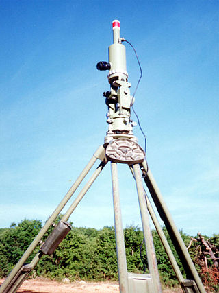
In surveying, a gyrotheodolite is an instrument composed of a gyrocompass mounted to a theodolite. It is used to determine the orientation of true north. It is the main instrument for orientation in mine surveying and in tunnel engineering, where astronomical star sights are not visible and GPS does not work.

<span class="mw-page-title-main">Inertial navigation system</span> Continuously computed dead reckoning

An inertial navigation system is a navigation device that uses motion sensors (accelerometers), rotation sensors (gyroscopes) and a computer to continuously calculate by dead reckoning the position, the orientation, and the velocity of a moving object without the need for external references. Often the inertial sensors are supplemented by a barometric altimeter and sometimes by magnetic sensors (magnetometers) and/or speed measuring devices. INSs are used on mobile robots and on vehicles such as ships, aircraft, submarines, guided missiles, and spacecraft. Older INS systems generally used an inertial platform as their mounting point to the vehicle and the terms are sometimes considered synonymous.

<span class="mw-page-title-main">Inertial measurement unit</span> Accelerometer-based navigational device

An inertial measurement unit (IMU) is an electronic device that measures and reports a body's specific force, angular rate, and sometimes the orientation of the body, using a combination of accelerometers, gyroscopes, and sometimes magnetometers. When the magnetometer is included, IMUs are referred to as IMMUs.

<span class="mw-page-title-main">Turn and slip indicator</span> Aircraft flight instrument

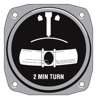
In aviation, the turn and slip indicator and the turn coordinator (TC) variant are essentially two aircraft flight instruments in one device. One indicates the rate of turn, or the rate of change in the aircraft's heading; the other part indicates whether the aircraft is in coordinated flight, showing the slip or skid of the turn. The slip indicator is actually an inclinometer that at rest displays the angle of the aircraft's transverse axis with respect to horizontal, and in motion displays this angle as modified by the acceleration of the aircraft. The most commonly used units are degrees per second (deg/s) or minutes per turn (min/tr).

References

Footnotes

  1. As a heading indicator ages and its ball bearings become worn and noisy, thus increasing friction, the tendency to drift will increase.

Notes

  1. Grumman F11F Tiger Pilot's Flight Operating Instructions. United States Navy. 1 September 2008. p. 51. ISBN   978-1-935327-46-2 . Retrieved 17 February 2022.
  2. Rotorcraft Flying Handbook FAA-H-8083-21A. Federal Aviation Authority. 2012. p. 12-3.
  3. Kjellstrom, Bjorn; Elgin, Carina Kjellstrom (9 December 2009). Be Expert with Map and Compass. John Wiley & Sons. p. 73. ISBN   978-0-470-40765-3 . Retrieved 17 February 2022.
  4. 1 2 3 4 Bowditch, Nathaniel. American Practical Navigator, Paradise Cay Publications, 2002, pp.93-94, ISBN   978-0-939837-54-0.
  5. "Inside the Cockpit of Amelia Earhart's Vega". airandspace.si.edu. Retrieved 17 February 2022.
  6. NASA NASA Callback: Heading for Trouble, NASA Callback Safety Bulletin website, December 2005, No. 305. Retrieved August 29, 2010.
  7. Instrument Flying Handbook, FAA-H-8083-15B (PDF). U.S. Dept. of Transportation, FAA. 2012. p. 5-19,5-20.
  8. Pilot's Handbook of Aeronautical Knowledge, FAA-H-8083-25B (PDF). U.S. Dept. of Transportation, FAA. 2016. p. 8-19,8-20.
  9. Peck, James L. H. (March 1944). "How Aircraft Instruments Work". Popular Science. Vol. 144, no. 3. New York, New York: Popular Science Publishing Company. p. 119. Retrieved 31 January 2023.