
Flight instruments are the instruments in the cockpit of an aircraft that provide the pilot with data about the flight situation of that aircraft, such as altitude, airspeed, vertical speed, heading and much more other crucial information in flight. They improve safety by allowing the pilot to fly the aircraft in level flight, and make turns, without a reference outside the aircraft such as the horizon. Visual flight rules (VFR) require an airspeed indicator, an altimeter, and a compass or other suitable magnetic direction indicator. Instrument flight rules (IFR) additionally require a gyroscopic pitch-bank, direction and rate of turn indicator, plus a slip-skid indicator, adjustable altimeter, and a clock. Flight into instrument meteorological conditions (IMC) require radio navigation instruments for precise takeoffs and landings.
Aviation is the design, development, production, operation, and use of aircraft, especially heavier-than-air aircraft. Articles related to aviation include:
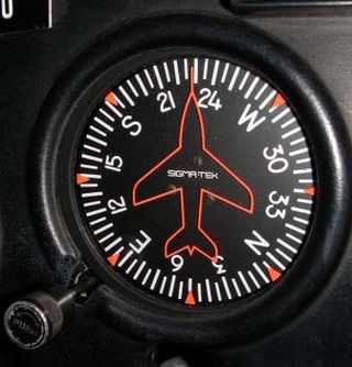
The heading indicator (HI), also known as a directional gyro (DG) or direction indicator (DI), is a flight instrument used in an aircraft to inform the pilot of the aircraft's heading.

The attitude indicator (AI), also known as the gyro horizon or artificial horizon, is a flight instrument that informs the pilot of the aircraft orientation relative to Earth's horizon, and gives an immediate indication of the smallest orientation change. The miniature aircraft and horizon bar mimic the relationship of the aircraft relative to the actual horizon. It is a primary instrument for flight in instrument meteorological conditions.

In flight dynamics a spin is a special category of stall resulting in autorotation about the aircraft's longitudinal axis and a shallow, rotating, downward path approximately centred on a vertical axis. Spins can be entered intentionally or unintentionally, from any flight attitude if the aircraft has sufficient yaw while at the stall point. In a normal spin, the wing on the inside of the turn stalls while the outside wing remains flying. It is possible for both wings to stall, but the angle of attack of each wing, and consequently its lift and drag, are different.

An autopilot is a system used to control the path of a vehicle without requiring constant manual control by a human operator. Autopilots do not replace human operators. Instead, the autopilot assists the operator's control of the vehicle, allowing the operator to focus on broader aspects of operations.

A head-up display, or heads-up display, also known as a HUD or head-up guidance system (HGS), is any transparent display that presents data without requiring users to look away from their usual viewpoints. The origin of the name stems from a pilot being able to view information with the head positioned "up" and looking forward, instead of angled down looking at lower instruments. A HUD also has the advantage that the pilot's eyes do not need to refocus to view the outside after looking at the optically nearer instruments.

A slip is an aerodynamic state where an aircraft is moving somewhat sideways as well as forward relative to the oncoming airflow or relative wind. In other words, for a conventional aircraft, the nose will be pointing in the opposite direction to the bank of the wing(s). The aircraft is not in coordinated flight and therefore is flying inefficiently.

An inclinometer or clinometer is an instrument used for measuring angles of slope, elevation, or depression of an object with respect to gravity's direction. It is also known as a tilt indicator, tilt sensor, tilt meter, slope alert, slope gauge, gradient meter, gradiometer, level gauge, level meter, declinometer, and pitch & roll indicator. Clinometers measure both inclines and declines using three different units of measure: degrees, percentage points, and topos. The astrolabe is an example of an inclinometer that was used for celestial navigation and location of astronomical objects from ancient times to the Renaissance.
In aviation, aircraft compass turns are turns made in an aircraft using only a magnetic compass for guidance.

In aviation, an electronic flight instrument system (EFIS) is a flight instrument display system in an aircraft cockpit that displays flight data electronically rather than electromechanically. An EFIS normally consists of a primary flight display (PFD), multi-function display (MFD), and an engine indicating and crew alerting system (EICAS) display. Early EFIS models used cathode-ray tube (CRT) displays, but liquid crystal displays (LCD) are now more common. The complex electromechanical attitude director indicator (ADI) and horizontal situation indicator (HSI) were the first candidates for replacement by EFIS. Now, however, few flight deck instruments cannot be replaced by an electronic display.

Aerobatic maneuvers are flight paths putting aircraft in unusual attitudes, in air shows, dogfights or competition aerobatics. Aerobatics can be performed by a single aircraft or in formation with several others. Nearly all aircraft are capable of performing aerobatics maneuvers of some kind, although it may not be legal or safe to do so in certain aircraft.

The Garmin G1000 is an electronic flight instrument system (EFIS) typically composed of two display units, one serving as a primary flight display, and one as a multi-function display. Manufactured by Garmin Aviation, it serves as a replacement for most conventional flight instruments and avionics. Introduced in June 2004, the system has since become one of the most popular integrated glass cockpit solutions for general aviation and business aircraft.
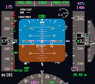
A primary flight display or PFD is a modern aircraft instrument dedicated to flight information. Much like multi-function displays, primary flight displays are built around a Liquid-crystal display or CRT display device. Representations of older six pack or "steam gauge" instruments are combined on one compact display, simplifying pilot workflow and streamlining cockpit layouts.
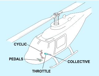
Helicopter flight controls are used to achieve and maintain controlled aerodynamic helicopter flight. Changes to the aircraft flight control system transmit mechanically to the rotor, producing aerodynamic effects on the rotor blades that make the helicopter move in a desired way. To tilt forward and back (pitch) or sideways (roll) requires that the controls alter the angle of attack of the main rotor blades cyclically during rotation, creating differing amounts of lift at different points in the cycle. To increase or decrease overall lift requires that the controls alter the angle of attack for all blades collectively by equal amounts at the same time, resulting in ascent, descent, acceleration and deceleration.

In aviation, coordinated flight of an aircraft is flight without sideslip.

The horizontal situation indicator is an aircraft flight instrument normally mounted below the artificial horizon in place of a conventional heading indicator. It combines a heading indicator with a VHF omnidirectional range-instrument landing system (VOR-ILS) display.
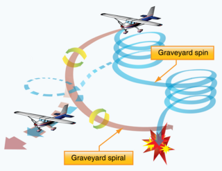
In aviation, a graveyard spiral is a type of dangerous spiral dive entered into accidentally by a pilot who is not trained or not proficient in flying in instrument meteorological conditions (IMC). Other names for this phenomenon include suicide spiral, deadly spiral, death spiral and vicious spiral.
The yaw string, also known as a slip string, is a simple device for indicating a slip or skid in an aircraft in flight. It performs the same function as the slip-skid indicator ball, but is more sensitive, and does not require the pilot to look down at the instrument panel. Technically, it measures sideslip angle, not yaw angle, but this indicates how the aircraft must be yawed to return the sideslip angle to zero.

The LN-3 inertial navigation system is an inertial navigation system (INS) that was developed in the 1960s by Litton Industries. It equipped the Lockheed F-104 Starfighter versions used as strike aircraft in European forces. An inertial navigation system is a system which continually determines the position of a vehicle from measurements made entirely within the vehicle using sensitive instruments. These instruments are accelerometers which detect and measure vehicle accelerations, and gyroscopes which act to hold the accelerometers in proper orientation.


