Flight instruments

Last updated
The cockpit of a Slingsby T-67 Firefly two-seat light airplane. The flight instruments are visible on the left of the instrument panel Slingsby.t67c.panel.g-bocm.arp.jpg
The cockpit of a Slingsby T-67 Firefly two-seat light airplane. The flight instruments are visible on the left of the instrument panel

Flight instruments are the instruments in the cockpit of an aircraft that provide the pilot with data about the flight situation of that aircraft, such as altitude, airspeed, vertical speed, heading and much more other crucial information in flight. They improve safety by allowing the pilot to fly the aircraft in level flight, and make turns, without a reference outside the aircraft such as the horizon. Visual flight rules (VFR) require an airspeed indicator, an altimeter, and a compass or other suitable magnetic direction indicator. Instrument flight rules (IFR) additionally require a gyroscopic pitch-bank (artificial horizon), direction (directional gyro) and rate of turn indicator, plus a slip-skid indicator, adjustable altimeter, and a clock. Flight into instrument meteorological conditions (IMC) require radio navigation instruments for precise takeoffs and landings. [1] :3–1

Contents

The term is sometimes used loosely as a synonym for cockpit instruments as a whole, in which context it can include engine instruments, navigational and communication equipment. Many modern aircraft have electronic flight instrument systems.

Most regulated aircraft have these flight instruments as dictated by the US Code of Federal Regulations, Title 14, Part 91. They are grouped according to pitot-static system, compass systems, and gyroscopic instruments. [1] :3–1

Pitot-static systems

Instruments which are pitot-static systems use air pressure differences to determine speed and altitude.

Altimeter

3-Pointer Altimeter.svg

The altimeter shows the aircraft's altitude above sea-level by measuring the difference between the pressure in a stack of aneroid capsules inside the altimeter and the atmospheric pressure obtained through the static system. The most common unit for altimeter calibration worldwide is hectopascals (hPa), except for North America and Japan where inches of mercury (inHg) are used. [2] The altimeter is adjustable for local barometric pressure which must be set correctly to obtain accurate altitude readings, usually in either feet or meters. As the aircraft ascends, the capsules expand and the static pressure drops, causing the altimeter to indicate a higher altitude. The opposite effect occurs when descending. With the advancement in aviation and increased altitude ceiling, the altimeter dial had to be altered for use both at higher and lower altitudes. Hence when the needles were indicating lower altitudes i.e. the first 360-degree operation of the pointers was delineated by the appearance of a small window with oblique lines warning the pilot that he or she is nearer to the ground. This modification was introduced in the early sixties after the recurrence of air accidents caused by the confusion in the pilot's mind. At higher altitudes, the window will disappear. [1] :3–3

Airspeed indicator

Airspeed indicator.svg

The airspeed indicator shows the aircraft's speed relative to the surrounding air. Knots is the currently most used unit, but kilometers per hour is sometimes used instead. The airspeed indicator works by measuring the ram-air pressure in the aircraft's pitot tube relative to the ambient static pressure. The indicated airspeed (IAS) must be corrected for nonstandard pressure and temperature in order to obtain the true airspeed (TAS). The instrument is color coded to indicate important airspeeds such as the stall speed, never-exceed airspeed, or safe flap operation speeds. [1] :3-7 to 3-8

Vertical speed indicator

Vertical speed indicator.PNG

The VSI (also sometimes called a variometer, or rate of climb indicator) senses changing air pressure, and displays that information to the pilot as a rate of climb or descent in feet per minute, meters per second or knots. [1] :3-8 to 3-9

Compass systems

Magnetic compass

Aero Magnetic Compass.jpg

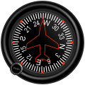
The compass shows the aircraft's heading relative to magnetic north. Errors include Variation, or the difference between magnetic and true direction, and Deviation, caused by the electrical wiring in the aircraft, which requires a Compass Correction Card. Additionally, the compass is subject to Dip Errors. While reliable in steady level flight it can give confusing indications when turning, climbing, descending, or accelerating due to the inclination of the Earth's magnetic field. For this reason, the heading indicator is also used for aircraft operation, but periodically calibrated against the compass. [1] :3-9 to 3-13,3–19

Gyroscopic systems

Attitude Indicator

Attitude indicator level flight.svg

The attitude indicator (also known as an artificial horizon) shows the aircraft's relation to the horizon. From this the pilot can tell whether the wings are level (roll) and if the aircraft nose is pointing above or below the horizon (pitch). [1] :3-18 to 3-19 Attitude is always presented to users in the unit degrees (°).[ citation needed ] The attitude indicator is a primary instrument for instrument flight and is also useful in conditions of poor visibility. Pilots are trained to use other instruments in combination should this instrument or its power fail.

Schempp-Hirth Janus-C glider Instrument panel equipped for "cloud flying". The turn and bank indicator is top centre. The heading indicator is replaced by a GPS-driven computer with wind and glide data, driving two electronic variometer displays to the right. Glider Instrument Panel.png
Schempp-Hirth Janus-C glider Instrument panel equipped for "cloud flying". The turn and bank indicator is top centre. The heading indicator is replaced by a GPS-driven computer with wind and glide data, driving two electronic variometer displays to the right.

Heading indicator

Heading indicator.svg

The heading indicator (also known as the directional gyro, or DG) displays the aircraft's heading in compass points, and with respect to magnetic north when set with a compass. Bearing friction causes drift errors from precession, which must be periodically corrected by calibrating the instrument to the magnetic compass. [1] :3-19 to 3-20 In many advanced aircraft (including almost all jet aircraft), the heading indicator is replaced by a horizontal situation indicator (HSI) which provides the same heading information, but also assists with navigation.

Turn indicator

Turn coordinator - coordinated.svg

These include the Turn-and-Slip Indicator and the Turn Coordinator, which indicate rotation about the longitudinal axis. They include an inclinometer to indicate if the aircraft is in Coordinated flight, or in a Slip or Skid. Additional marks indicate a Standard rate turn. [1] :3-20 to 3-22 The turn rate is most commonly expressed in either degrees per second (deg/s) or minutes per turn (min/tr).[ citation needed ]

Flight director systems

These include the Horizontal Situation Indicator (HSI) and Attitude Director Indicator (ADI). The HSI combines the magnetic compass with navigation signals and a Glide slope. The navigation information comes from a VOR/Localizer, or GNSS. The ADI is an Attitude Indicator with computer-driven steering bars, a task reliever during instrument flight. [1] :3-22 to 3-23,7–10

Very-High Frequency Omnidirectional Range (VOR)

Vor indicator.png

The VOR indicator instrument includes a Course deviation indicator (CDI), Omnibearing Selector (OBS), TO/FROM indicator, and Flags. The CDI shows an aircraft's lateral position in relation to a selected radial track. It is used for orientation, tracking to or from a station, and course interception. [1] :7-8 to 7-11 On the instrument, the vertical needle indicates the lateral position of the selected track. A horizontal needle allows the pilot to follow a glide slope when the instrument is used with an ILS.

Nondirectional Radio Beacon (NDB)

Adf rmi.jpg

The Automatic direction finder (ADF) indicator instrument can be a fixed-card, movable card, or a Radio magnetic indicator (RMI). An RMI is remotely coupled to a gyrocompass so that it automatically rotates the azimuth card to represent aircraft heading. [1] :7-3 to 7-4 While simple ADF displays may have only one needle, a typical RMI has two, coupled to different ADF receivers, allowing for position fixing using one instrument.

Layout

Six basic instruments in a light twin-engine airplane arranged in a "basic-T". From top left: airspeed indicator, attitude indicator, altimeter, turn coordinator, heading indicator, and vertical speed indicator Six flight instruments.JPG
Six basic instruments in a light twin-engine airplane arranged in a "basic-T". From top left: airspeed indicator, attitude indicator, altimeter, turn coordinator, heading indicator, and vertical speed indicator

Most aircraft are equipped with a standard set of flight instruments which give the pilot information about the aircraft's attitude, airspeed, and altitude.

T arrangement

Most US aircraft built since the 1940s have flight instruments arranged in a standardized pattern called the "T" arrangement. [3] The attitude indicator is in the top center, airspeed to the left, altimeter to the right and heading indicator under the attitude indicator. The other two, turn-coordinator and vertical-speed, are usually found under the airspeed and altimeter, but are given more latitude in placement. The magnetic compass will be above the instrument panel, often on the windscreen centerpost. In newer aircraft with glass cockpit instruments the layout of the displays conform to the basic T arrangement.

Early history

In 1929, Jimmy Doolittle became the first pilot to take off, fly and land an airplane using instruments alone, without a view outside the cockpit. In 1937, the British Royal Air Force (RAF) chose a set of six essential flight instruments [4] which would remain the standard panel used for flying in instrument meteorological conditions (IMC) for the next 20 years. They were:

This panel arrangement was incorporated into all RAF aircraft built to official specification from 1938, such as the Miles Master, Hawker Hurricane, Supermarine Spitfire, and 4-engined Avro Lancaster and Handley Page Halifax heavy bombers, but not the earlier light single-engined Tiger Moth trainer, and minimized the type-conversion difficulties associated with blind flying, since a pilot trained on one aircraft could quickly become accustomed to any other if the instruments were identical.

This basic six set, also known as a "six pack", [5] was also adopted by commercial aviation. After the Second World War the arrangement was changed to: (top row) airspeed, artificial horizon, altimeter, (bottom row) turn and bank indicator, heading indicator, vertical speed.

Further development

Primary Flight Display (PFD) PFD.png
Primary Flight Display (PFD)

In glass cockpits the flight instruments are shown on monitors. Primary flight display, is given a central place on the panel, superseding the artificial horizon, often, with a horizontal situation indicator next to it or integrated with the PFD. The indicated airspeed, altimeter, and vertical speed indicator are displayed as moving "tapes" with the indicated airspeed to the left of the horizon and the altimeter and the vertical speed to the right in the same layout as in most older style "clock cockpits".

See also

Related Research Articles

<span class="mw-page-title-main">Pitot tube</span> Device which measures fluid flow velocity, typically around an aircraft or boat

A pitot tube measures fluid flow velocity. It was invented by a French engineer, Henri Pitot, in the early 18th century, and was modified to its modern form in the mid-19th century by a French scientist, Henry Darcy. It is widely used to determine the airspeed of aircraft; the water speed of boats; and the flow velocity of liquids, air, and gases in industry.

<span class="mw-page-title-main">Variometer</span> Flight instrument which determines the aircrafts vertical velocity (rate of descent/climb)

In aviation, a variometer – also known as a rate of climb and descent indicator (RCDI), rate-of-climb indicator, vertical speed indicator (VSI), or vertical velocity indicator (VVI) – is one of the flight instruments in an aircraft used to inform the pilot of the rate of descent or climb. It can be calibrated in metres per second, feet per minute or knots, depending on country and type of aircraft. It is typically connected to the aircraft's external static pressure source.

Aviation is the design, development, production, operation, and use of aircraft, especially heavier-than-air aircraft. Articles related to aviation include:

<span class="mw-page-title-main">Airspeed indicator</span> Flight instrument

The airspeed indicator (ASI) or airspeed gauge is a flight instrument indicating the airspeed of an aircraft in kilometres per hour (km/h), knots (kn), miles per hour (MPH) and/or metres per second (m/s). The recommendation by ICAO is to use km/h, however knots is currently the most used unit. The ASI measures the pressure differential between static pressure from the static port, and total pressure from the pitot tube. This difference in pressure is registered with the ASI pointer on the face of the instrument.

<span class="mw-page-title-main">Heading indicator</span> Type of aircraft flight instrument

The heading indicator (HI), also known as a directional gyro (DG) or direction indicator (DI), is a flight instrument used in an aircraft to inform the pilot of the aircraft's heading.

<span class="mw-page-title-main">Attitude indicator</span> Flight instrument which displays the aircrafts orientation relative to Earths horizon

The attitude indicator (AI), formerly known as the gyro horizon or artificial horizon, is a flight instrument that informs the pilot of the aircraft orientation relative to Earth's horizon, and gives an immediate indication of the smallest orientation change. The miniature aircraft and horizon bar mimic the relationship of the aircraft relative to the actual horizon. It is a primary instrument for flight in instrument meteorological conditions.

<span class="mw-page-title-main">Aeroperú Flight 603</span> 1996 aviation accident

Aeroperú Flight 603 (PL603/PLI603) was a scheduled passenger flight from Miami International Airport in Miami, Florida, to Arturo Merino Benítez International Airport in Santiago, Chile, with stopovers in Quito, Ecuador, and Lima, Peru. On October 2, 1996, the Boeing 757-23A aircraft flying the final leg of the flight crashed, killing all 70 people aboard.

<span class="mw-page-title-main">Airspeed</span> Speed of an aircraft relative to the surrounding air

In aviation, airspeed is the speed of an aircraft relative to the air it is flying through. It is difficult to measure the exact airspeed of the aircraft, but other measures of airspeed, such as indicated airspeed and Mach number give useful information about the capabilities and limitations of airplane performance. The common measures of airspeed are:

<span class="mw-page-title-main">Indicated airspeed</span> Displayed on the airspeed indicator on an aircraft

Indicated airspeed (IAS) is the airspeed of an aircraft as measured by its pitot-static system and displayed by the airspeed indicator (ASI). This is the pilots' primary airspeed reference.

<span class="mw-page-title-main">Instrument landing system localizer</span> Horizontal guidance system

An instrument landing system localizer, or simply localizer, is a system of horizontal guidance in the instrument landing system, which is used to guide aircraft along the axis of the runway.

In aviation, aircraft compass turns are turns made in an aircraft using only a magnetic compass for guidance.

Position error is one of the errors affecting the systems in an aircraft for measuring airspeed and altitude. It is not practical or necessary for an aircraft to have an airspeed indicating system and an altitude indicating system that are exactly accurate. A small amount of error is tolerable. It is caused by the location of the static vent that supplies air pressure to the airspeed indicator and altimeter; there is no position on an aircraft where, at all angles of attack, the static pressure is always equal to atmospheric pressure.

<span class="mw-page-title-main">Electronic flight instrument system</span> Display system in an aircrafts cockpit which displays flight information electronically

In aviation, an electronic flight instrument system (EFIS) is a flight instrument display system in an aircraft cockpit that displays flight data electronically rather than electromechanically. An EFIS normally consists of a primary flight display (PFD), multi-function display (MFD), and an engine indicating and crew alerting system (EICAS) display. Early EFIS models used cathode ray tube (CRT) displays, but liquid crystal displays (LCD) are now more common. The complex electromechanical attitude director indicator (ADI) and horizontal situation indicator (HSI) were the first candidates for replacement by EFIS. Now, however, few flight deck instruments cannot be replaced by an electronic display.

<span class="mw-page-title-main">Garmin G1000</span> Electronic flight instrument system

The Garmin G1000 is an electronic flight instrument system (EFIS) typically composed of two display units, one serving as a primary flight display, and one as a multi-function display. Manufactured by Garmin Aviation, it serves as a replacement for most conventional flight instruments and avionics. Introduced in June 2004, the system has since become one of the most popular integrated glass cockpit solutions for general aviation and business aircraft.

<span class="mw-page-title-main">Pitot–static system</span> System of pressure-sensitive instruments used to determine an aircrafts speed, altitude, etc.

A pitot–static system is a system of pressure-sensitive instruments that is most often used in aviation to determine an aircraft's airspeed, Mach number, altitude, and altitude trend. A pitot–static system generally consists of a pitot tube, a static port, and the pitot–static instruments. Other instruments that might be connected are air data computers, flight data recorders, altitude encoders, cabin pressurization controllers, and various airspeed switches. Errors in pitot–static system readings can be extremely dangerous as the information obtained from the pitot static system, such as altitude, is potentially safety-critical. Several commercial airline disasters have been traced to a failure of the pitot–static system.

<span class="mw-page-title-main">Air data computer</span> Avionics component

An air data computer (ADC) or central air data computer (CADC) computes altitude, vertical speed, air speed, and Mach number from pressure and temperature inputs. It is an essential avionics component found in modern aircraft. This computer, rather than individual instruments, can determine the calibrated airspeed, Mach number, altitude, and altitude trend data from an aircraft's pitot-static system. In some very high-speed aircraft such as the Space Shuttle, equivalent airspeed is calculated instead of calibrated airspeed.

<span class="mw-page-title-main">Primary flight display</span> Modern aircraft instrument

A primary flight display or PFD is a modern aircraft instrument dedicated to flight information. Much like multi-function displays, primary flight displays are built around a Liquid-crystal display or CRT display device. Representations of older six pack or "steam gauge" instruments are combined on one compact display, simplifying pilot workflow and streamlining cockpit layouts.

<span class="mw-page-title-main">Machmeter</span> Flight instrument

A Machmeter is an aircraft pitot-static system flight instrument that shows the ratio of the true airspeed to the speed of sound, a dimensionless quantity called Mach number. This is shown on a Machmeter as a decimal fraction. An aircraft flying at the speed of sound is flying at a Mach number of one, expressed as Mach 1.

A blind flying panel is an instrumentation sub-panel located in the cockpit of an aircraft. Its purpose was to present the necessary information to pilots for flying under instrument flight rules (IFR); it would be used in circumstances where visual flight rules (VFR) would not be desirable or possible, such as during night time or unclear weather conditions. The blind flying panel was prevalently used during the Second World War upon a wide range of aircraft, from fighters such as the Supermarine Spitfire, to bombers and trainers alike. In the postwar era, it decreased in relevance following the increasing prevalence of onboard radar sets and other newer navigational aids.

<span class="mw-page-title-main">Turn and slip indicator</span> Aircraft flight instrument

In aviation, the turn and slip indicator and the turn coordinator (TC) variant are essentially two aircraft flight instruments in one device. One indicates the rate of turn, or the rate of change in the aircraft's heading; the other part indicates whether the aircraft is in coordinated flight, showing the slip or skid of the turn. The slip indicator is actually an inclinometer that at rest displays the angle of the aircraft's transverse axis with respect to horizontal, and in motion displays this angle as modified by the acceleration of the aircraft. The most commonly used units are degrees per second (deg/s) or minutes per turn (min/tr).

References

  1. 1 2 3 4 5 6 7 8 9 10 11 12 Instrument Flying Handbook, 2001, FAA-H-8083-15, US Dept. of Transportation, Federal Aviation Administration, Flight Standards Service
  2. Aviation's Crazy, Mixed Up Units of Measure - AeroSavvy
  3. Mark Natola, ed. (2002). Boeing B-47 Stratojet. Schiffer Publishing Ltd. p. 46. ISBN   0764316702.
  4. Williamson, G. W. (19 August 1937). "Instrument Planning: The New Service Blind-Flying Panel Described". Flight. p. 193. Archived from the original on 27 July 2014. Retrieved 3 May 2024.
  5. "Six Pack - The Primary Flight Instruments". LearnToFly.ca. 13 March 2010. Retrieved 31 January 2011.