Leading-edge cuff

Last updated

A drooped leading-edge cuff installed on an American Aviation AA-1 Yankee as part of a NASA experiment DroopedLeadingEdgeCuff01.JPG
A drooped leading-edge cuff installed on an American Aviation AA-1 Yankee as part of a NASA experiment

A leading-edge cuff is a fixed aerodynamic wing device employed on fixed-wing aircraft to improve the stall and spin characteristics. Cuffs may be either factory-designed or an after-market add-on modification. [1]

Contents

A leading-edge cuff is a wing leading-edge modification, usually a lightly drooped outboard leading-edge extension. In most cases of outboard leading-edge modification, the wing cuff starts about 50–70% half-span and spans the outer leading edge of the wing. [2]

The main goal is to produce a more gradual and gentler stall onset, without any spin departure tendency, particularly where the original wing has a sharp/asymmetric stall behaviour [1] [3] with a passive, non-moving, low-cost device that would have a minimal impact on performance. A further benefit is to lowering stall speed, with lower approach speeds and shorter landing distances. They may also, depending on cuff location, improve aileron control at low speed.

Terminology

Leading-edge cuffs were called droop concept or drooped leading edge (DLE), or modified outboard leading edge in technical reports on stall/spin resistance. [4] In these reports and others NASA reports on the same object, [5] "leading-edge cuff" expression was not used.

Other authors use simply "cuff" or "wing cuff". [6]

History

NASA led a general aviation stall/spin research program during the 1970s and 1980s, using model and full-scale experiments, seeking an effective means to improve stall/spin characteristics of general aviation airplanes. [7]

The effect of a central notch at mid-span on the wing maximum lift was demonstrated in 1976. [8] Following the testing of different leading-edge modifications on models and full-sized aircraft NASA eventually selected the semi-span drooped leading edge (DLE) that was tested first on an American Aviation AA-1 Yankee (1978).

A 1979 NASA report [9] explains that at high angles of attack the cuff discontinuity generates a vortex that acts as a fence, preventing the separated flow from progressing outboard. The lift slope has a flatter top and the stall angle is delayed to a higher angle. To reach high angles of attack, the outboard airfoil has to be drooped, some experiments investigating "exaggerated" drooped leading edges. The physical reason for the cuff effect was not clearly explained. [10]

Some much older reports gave some similar results. A 1932 NACA report [11] about the effect of leading-edge slots of various lengths said, "this is an indication that the slotted portion on each tip of the wing operates to some extent as a separate wing".

Getting higher lift coefficients as a result of boundary layer removal is well known on propellers (centrifugal force causing an outward displacement of the boundary layer), [12] or wings (boundary-layer suction). The leading-edge cuff inboard vortex and wing tip vortex act both to remove the boundary layer of the wing's outer section, helping this low-aspect-ratio virtual wing to achieve a higher stall angle. [13]

An important point is that the wing seems to be aerodynamically split in two parts, the inner stalled part and the outer part that behaves as an isolated low-aspect-ratio wing, able to reach a high angle of attack. The sharp discontinuity of the cuff is a key factor; all attempts by gradual fairing to suppress the vortex and the positive effects of the modification reintroduced an abrupt tip stall. [14]

Stall/spin results

According to a NASA stall/spin report, "The basic airplanes: AA-1 (Yankee), C-23 (Sundowner), PA-28 (Arrow), C-172 (Skyhawk) entered spins in 59 to 98 percent of the intentional spin-entry attempts, whereas the modified aircraft entered spins in only 5 percent of the attempts and required prolonged, aggravated control inputs or out-of-limit loadings to promote spin entry." [15]

Wing aspect ratio and location effects

The most successful NASA experimental results were obtained on a quite low 6:1 aspect ratio wing (Grumman Yankee AA-1), with a DLE placed at 57% of the semi-span. As the vortices (inboard cuff and wing tip) are efficient on a limited span length (about 1.5 times the local chord), a DLE alone is unable to preserve enough outboard lift to keep the roll control in case of high aspect ratio wing. [16] Wings of more than 8 or 9 aspect ratio features other devices to complete the cuff effect, [17] for example stall strips (as used on the Cirrus SR22 and Cessna 400), "Rao slots" (as used on the Questair Venture), vortex generators or segmented droop (as used on a NASA modified Cessna 210). In the case of the high aspect ratio Cessna 210 wing (AR =11:1), roll damping at stall was not as efficient. [18]

The case of high-wing configuration wing was different. Full scale testing of a modified Cessna 172 showed that the outboard leading-edge cuff alone was not sufficient to prevent a spin departure, the aircraft lacking directional stability at high angles of attack. With a ventral fin added, the aircraft entered a controlled spiral in lieu of a spin. [19]

Drag penalty

Depending on the cuff length and shape, the leading-edge cuff can exert an aerodynamic penalty for the stall/spin resistance speed obtained, resulting in some loss of cruise airspeed, although sometimes too small "to be detected with production instruments". [20] In the case of the best wing modification of the AA-1 Yankee, the loss of cruise speed amounted to 2 mph or 2% and there was no speed loss in climb. [21] Impact on cruise speed of the Piper PA-28 RX (modified T-tail) was not measurable. [22] For the Questair Venture, "In carefully controlled performance tests, the penalty in cruise performance was found to be imperceptible (1 kt)". [23]

Applications

The first use of outboard cuffs, other than on NASA research airplanes, was on the Rutan VariEze in 1978. They were wind tunnel tested in 1982, and later (1984) replaced by vortilons. [24]

Following aircraft were modified for experiments with the addition of an outboard leading-edge cuff as a result of NASA stall/spin research program :

Leading-edge cuffs are used on 1900s high-performance light aircraft like the Cirrus SR20 and Columbia 350, which both gained FAA-certification with the device. [32] [33]

Several after-market suppliers of STOL kits make use of leading-edge cuffs, in some cases in conjunction with such other aerodynamic devices as wing fences and drooping ailerons. [34]

See also

Related Research Articles

<span class="mw-page-title-main">Wing</span> Surface used for flight, for example by insects, birds, bats and airplanes

A wing is a type of fin that produces lift while moving through air or some other fluid. Accordingly, wings have streamlined cross-sections that are subject to aerodynamic forces and act as airfoils. A wing's aerodynamic efficiency is expressed as its lift-to-drag ratio. The lift a wing generates at a given speed and angle of attack can be one to two orders of magnitude greater than the total drag on the wing. A high lift-to-drag ratio requires a significantly smaller thrust to propel the wings through the air at sufficient lift.

<span class="mw-page-title-main">Stall (fluid dynamics)</span> Abrupt reduction in lift due to flow separation

In fluid dynamics, a stall is a reduction in the lift coefficient generated by a foil as angle of attack increases. This occurs when the critical angle of attack of the foil is exceeded. The critical angle of attack is typically about 15°, but it may vary significantly depending on the fluid, foil, and Reynolds number.

<span class="mw-page-title-main">Delta wing</span> Triangle shaped aircraft wing configuration

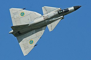
A delta wing is a wing shaped in the form of a triangle. It is named for its similarity in shape to the Greek uppercase letter delta (Δ).

<span class="mw-page-title-main">STOL</span> Class of airplanes that are designed to takeoff and land in a short distance

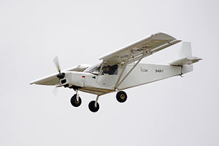
A short takeoff and landing (STOL) aircraft is a conventional fixed-wing aircraft that has short runway requirements for takeoff and landing. Many STOL-designed aircraft also feature various arrangements for use on airstrips with harsh conditions. STOL aircraft, including those used in scheduled passenger airline operations, have also been operated from STOLport airfields which feature short runways.

<span class="mw-page-title-main">Angle of attack</span> Angle between the chord of a wing and the undisturbed airflow

In fluid dynamics, angle of attack is the angle between a reference line on a body and the vector representing the relative motion between the body and the fluid through which it is moving. Angle of attack is the angle between the body's reference line and the oncoming flow. This article focuses on the most common application, the angle of attack of a wing or airfoil moving through air.

<span class="mw-page-title-main">Leading-edge extension</span> Anti-stall control surface on aircraft

A leading-edge extension (LEX) is a small extension to an aircraft wing surface, forward of the leading edge. The primary reason for adding an extension is to improve the airflow at high angles of attack and low airspeeds, to improve handling and delay the stall. A dog tooth can also improve airflow and reduce drag at higher speeds.

<span class="mw-page-title-main">Vortex generator</span> Aerodynamic device

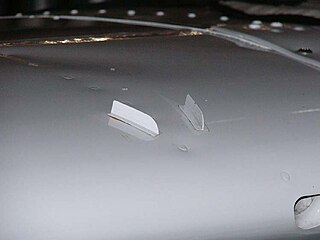
A vortex generator (VG) is an aerodynamic device, consisting of a small vane usually attached to a lifting surface or a rotor blade of a wind turbine. VGs may also be attached to some part of an aerodynamic vehicle such as an aircraft fuselage or a car. When the airfoil or the body is in motion relative to the air, the VG creates a vortex, which, by removing some part of the slow-moving boundary layer in contact with the airfoil surface, delays local flow separation and aerodynamic stalling, thereby improving the effectiveness of wings and control surfaces, such as flaps, elevators, ailerons, and rudders.

<span class="mw-page-title-main">Airfoil</span> Cross-sectional shape of a wing, blade of a propeller, rotor, or turbine, or sail

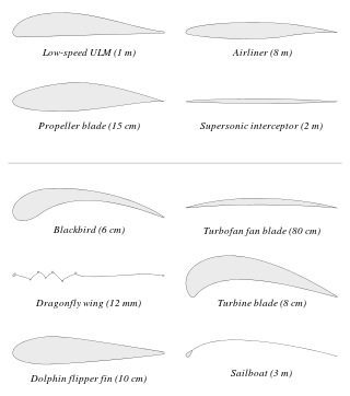
An airfoil or aerofoil is the cross-sectional shape of an object whose motion through a gas is capable of generating significant lift, such as a wing, a sail, or the blades of propeller, rotor, or turbine.

<span class="mw-page-title-main">Wingtip device</span> Aircraft component fixed to the end of the wings to improve performance

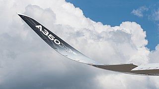
Wingtip devices are intended to improve the efficiency of fixed-wing aircraft by reducing drag. Although there are several types of wing tip devices which function in different manners, their intended effect is always to reduce an aircraft's drag by partial recovery of the tip vortex energy. Wingtip devices can also improve aircraft handling characteristics and enhance safety for following aircraft. Such devices increase the effective aspect ratio of a wing without greatly increasing the wingspan. Extending the span would lower lift-induced drag, but would increase parasitic drag and would require boosting the strength and weight of the wing. At some point, there is no net benefit from further increased span. There may also be operational considerations that limit the allowable wingspan.

<span class="mw-page-title-main">Spin (aerodynamics)</span> Aviation term for a corkscrew downward path

In flight dynamics a spin is a special category of stall resulting in autorotation about the aircraft's longitudinal axis and a shallow, rotating, downward path approximately centred on a vertical axis. Spins can be entered intentionally or unintentionally, from any flight attitude if the aircraft has sufficient yaw while at the stall point. In a normal spin, the wing on the inside of the turn stalls while the outside wing remains flying. It is possible for both wings to stall, but the angle of attack of each wing, and consequently its lift and drag, are different.

<span class="mw-page-title-main">Flap (aeronautics)</span> Anti-stalling high-lift device on aircraft

A flap is a high-lift device used to reduce the stalling speed of an aircraft wing at a given weight. Flaps are usually mounted on the wing trailing edges of a fixed-wing aircraft. Flaps are used to reduce the take-off distance and the landing distance. Flaps also cause an increase in drag so they are retracted when not needed.

<span class="mw-page-title-main">Grumman American AA-1</span> American light aircraft

The Grumman American AA-1 series is a family of light, two-seat aircraft. The family includes the original American Aviation AA-1 Yankee and AA-1A Trainer, the Grumman American AA-1B Trainer and TR-2, plus the Gulfstream American AA-1C Lynx and T-Cat.

<span class="mw-page-title-main">Leading-edge slot</span> Anti-stall control surface on aircraft

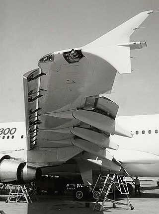
A leading-edge slot is a fixed aerodynamic feature of the wing of some aircraft to reduce the stall speed and promote good low-speed handling qualities. A leading-edge slot is a spanwise gap in each wing, allowing air to flow from below the wing to its upper surface. In this manner they allow flight at higher angles of attack and thus reduce the stall speed.

<span class="mw-page-title-main">Stall strips</span>

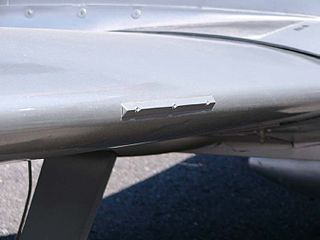
A stall strip is a small component fixed to the leading edge of the wing of an airplane to modify its aerodynamic characteristics. These stall strips may be necessary for the airplane to comply with type certification requirements.

<span class="mw-page-title-main">Canard (aeronautics)</span> Aircraft configuration in which a small wing is placed in front of the main wing

In aeronautics, a canard is a wing configuration in which a small forewing or foreplane is placed forward of the main wing of a fixed-wing aircraft or a weapon. The term "canard" may be used to describe the aircraft itself, the wing configuration, or the foreplane. Canard wings are also extensively used in guided missiles and smart bombs.

<span class="mw-page-title-main">Washout (aeronautics)</span> Characteristic of aircraft wing design

Washout is a characteristic of aircraft wing design which deliberately reduces the lift distribution across the span of an aircraft’s wing. The wing is designed so that the angle of incidence is greater at the wing roots and decreases across the span, becoming lowest at the wing tip. This is usually to ensure that at stall speed the wing root stalls before the wing tips, providing the aircraft with continued aileron control and some resistance to spinning. Washout may also be used to modify the spanwise lift distribution to reduce lift-induced drag.

<span class="mw-page-title-main">Wing configuration</span> Describes the general shape and layout of an aircraft wing

The wing configuration of a fixed-wing aircraft is its arrangement of lifting and related surfaces.

<span class="mw-page-title-main">Strake (aeronautics)</span> Flight control surface

In aviation, a strake is an aerodynamic surface generally mounted on the fuselage of an aircraft to improve the flight characteristics either by controlling the airflow or by a simple stabilising effect.

<span class="mw-page-title-main">Vortilon</span> Aerodynamic device

Vortilons are fixed aerodynamic devices on aircraft wings used to improve handling at low speeds.

<span class="mw-page-title-main">Leading edge</span> Foremost part of a wing or tail surface

The leading edge of an airfoil surface such as a wing is its foremost edge and is therefore the part which first meets the oncoming air.

References

  1. 1 2 Crane, Dale: Dictionary of Aeronautical Terms, third edition, page 144. Aviation Supplies & Academics, 1997. ISBN   1-56027-287-2
  2. Location referred to half-span : Beech C23 0.54, Piper PA-28 0.55, Yankee AA-1 0.57, Cirrus SR20 0.61, Lancair 300 0.66, Questair Venture 0.70, Cessna 172 0.71 - according to SAE TP 2000-01-1691, page 14
  3. Cox, Jack (November 1988). "Questair Venture, Part Two" . Retrieved 8 August 2009.
  4. Stough, DiCarlo Spin Resistance Development for Small Airplanes - A Retrospective, SAE TP 2000-01-1691 or "Nasa Stall Spin Paper from 1970s, or .
  5. Nasa TP 2011 (Yankee AA-1), Nasa TP 2772 (Cessna 210)
  6. Burt Rutan, Canard Pusher n°19 (1979), "Wing cuff improves VariEze stalls" or more recent Wing Cuff Design for Cessna CJ1
  7. H. Paul Stough III and Daniel J. DiCarlo, Spin Resistance Development for Small Airplanes - A Retrospective, SAE TP series 2000-01-1691
  8. Kroeger, R. A.; and Feistel, T, Reduction of stall-spin Entry Tendencies Through Wing Aerodynamic Design, SAE paper 760481
  9. NASA TP 1589, Wind-Tunnel Investigation of a Full-Scale General Aviation Airplane Equipped With an Advanced Natural Laminar Flow Wing
  10. NASA TP 1589 : "The mechanism by which the outer-panel lift is maintained to such improved stall/spin characteristics has been unclear".
  11. NACA TN 423, Weick, Fred E. Investigation of lateral control near the stall flight investigation with a light high-wing monoplane tested with various amounts of washout and various lengths of leading-edge slot.
  12. Hoerner, Fluid Dynamic lift, 12-24
  13. Zimmerman, NACA TN 539, 1935 , "Aerodynamic characteristics of several airfoils of low aspect ratio". "The preservation of unturbuled flow to very high angles of attack ... is apparently due to the action of the tip vortices in removing the boundary layer that ends to built up near the trailing edge of the upper surface of the airfoil".
  14. Addition of a fairing ... to eliminate the discontinuity reintroduced abrupt tip stall (SAE TP 2000-01-1691)
  15. Summary of results for spin attempts for four NASA research aircraft.,
  16. Barnaby Wainfan, KitPlanes July 1998, Wind Tunnel, Foiling stalls is the month's topic : "It has been found that the single-droop cuff configuration described in NASA TP 1589 is not sufficient to prevent spins on high ratio wings."
  17. Murri, Jordan, Nasa TP 2772, Wind-Tunnel Investigation of a Full-Scale General Aviation Airplane Equipped With an Advanced Natural Laminar Flow Wing (Cessna 210), Leading-Edge Modifications, p.9, "The data for the outboard-droop configuration show significantly enhanced roll damping characteristics at the stall; however, unstable roll damping characteristics are not completely eliminated with the outboard droop alone."
  18. NASA TP 2722, "... an unsteady stalling and reattaching behavior occurring inboard on the wing upper surface as wing stall progressed."
  19. Investigations of modifications to improve the spin resistance of a high-wing, single engine, light airplane, SAE Paper 891039 (1989)
  20. H. Holmes, Nasa's general aviation stall/spin program, Sport Aviation, January 1989
  21. Effects of Wing-Leading-Edge Modifications on a Full-Scale, Low-Wing General Aviation Airplane, Nasa TP 2011, Drag characteristics, p. 13
  22. Nasa TP 2691, Flight Investigation of the Effects of an Outboard Wing-Leading-Edge Modification on Stall/Spin Characteristics of a Low-Wing, Single-Engine, T-Tail Light Airplane : "within the measurement accuracy, no difference was found in airplane drag for lift coefficients typical of cruising flight."
  23. "Spin Resistance" (PDF). whycirrus.com.
  24. Rutan VariEze, NASA TP 2382 (1985) et NASA TP 2623 (1986)
  25. NASA TP 1589, Nasa TP 2011
  26. NASA CT 3636, NASA TP 2691
  27. SAE paper 891039
  28. AIAA 86-2596
  29. Sport Aviation Nov. 88. Meyer et Yip, AIAA 89-2237-CP report.
  30. NASA TP 2772
  31. DOT/FAA/CT-92/17, AIAA/FAA Joint symposium on GA
  32. "Data". grumman.net.
  33. Cessna (2009). "This beauty is more than skin deep". Archived from the original on 26 July 2009. Retrieved 8 August 2009.
  34. Horton Inc (n.d.). "Description of the Horton STOL Kit". Archived from the original on 21 November 2008. Retrieved 8 August 2009.