Cantilever

Last updated
A schematic image of three types of cantilever. The top example has a full moment connection (like a horizontal flagpole bolted to the side of a building). The middle example is created by an extension of a simple supported beam (such as the way a diving board is anchored and extends over the edge of a swimming pool). The bottom example is created by adding a Robin boundary condition to the beam element, which essentially adds an elastic spring to the end board. The top and bottom example may be considered structurally equivalent, depending on the effective stiffness of the spring and beam element. Cantilever examples.svg
A schematic image of three types of cantilever. The top example has a full moment connection (like a horizontal flagpole bolted to the side of a building). The middle example is created by an extension of a simple supported beam (such as the way a diving board is anchored and extends over the edge of a swimming pool). The bottom example is created by adding a Robin boundary condition to the beam element, which essentially adds an elastic spring to the end board. The top and bottom example may be considered structurally equivalent, depending on the effective stiffness of the spring and beam element.

A cantilever is a rigid structural element that extends horizontally and is unsupported at one end. Typically it extends from a flat vertical surface such as a wall, to which it must be firmly attached. Like other structural elements, a cantilever can be formed as a beam, plate, truss, or slab.

Contents

When subjected to a structural load at its far, unsupported end, the cantilever carries the load to the support where it applies a shear stress and a bending moment. [1]

Cantilever construction allows overhanging structures without additional support.

In bridges, towers, and buildings

Cantilevers are widely found in construction, notably in cantilever bridges and balconies (see corbel). In cantilever bridges, the cantilevers are usually built as pairs, with each cantilever used to support one end of a central section. The Forth Bridge in Scotland is an example of a cantilever truss bridge. A cantilever in a traditionally timber framed building is called a jetty or forebay. In the southern United States, a historic barn type is the cantilever barn of log construction.

Temporary cantilevers are often used in construction. The partially constructed structure creates a cantilever, but the completed structure does not act as a cantilever. This is very helpful when temporary supports, or falsework, cannot be used to support the structure while it is being built (e.g., over a busy roadway or river, or in a deep valley). Therefore, some truss arch bridges (see Navajo Bridge) are built from each side as cantilevers until the spans reach each other and are then jacked apart to stress them in compression before finally joining. Nearly all cable-stayed bridges are built using cantilevers as this is one of their chief advantages. Many box girder bridges are built segmentally, or in short pieces. This type of construction lends itself well to balanced cantilever construction where the bridge is built in both directions from a single support.

These structures rely heavily on torque and rotational equilibrium for their stability.

In an architectural application, Frank Lloyd Wright's Fallingwater used cantilevers to project large balconies. The East Stand at Elland Road Stadium in Leeds was, when completed, the largest cantilever stand in the world [2] holding 17,000 spectators. The roof built over the stands at Old Trafford uses a cantilever so that no supports will block views of the field. The old (now demolished) Miami Stadium had a similar roof over the spectator area. The largest cantilevered roof in Europe is located at St James' Park in Newcastle-Upon-Tyne, the home stadium of Newcastle United F.C. [3] [4]

Less obvious examples of cantilevers are free-standing (vertical) radio towers without guy-wires, and chimneys, which resist being blown over by the wind through cantilever action at their base.

Aircraft

The pioneering Junkers J 1 all-metal monoplane of 1915, the first aircraft to fly with cantilever wings Junkers J 1 at Doberitz 1915.jpg
The pioneering Junkers J 1 all-metal monoplane of 1915, the first aircraft to fly with cantilever wings

The cantilever is commonly used in the wings of fixed-wing aircraft. Early aircraft had light structures which were braced with wires and struts. However, these introduced aerodynamic drag which limited performance. While it is heavier, the cantilever avoids this issue and allows the plane to fly faster.

Hugo Junkers pioneered the cantilever wing in 1915. Only a dozen years after the Wright Brothers' initial flights, Junkers endeavored to eliminate virtually all major external bracing members in order to decrease airframe drag in flight. The result of this endeavor was the Junkers J 1 pioneering all-metal monoplane of late 1915, designed from the start with all-metal cantilever wing panels. About a year after the initial success of the Junkers J 1, Reinhold Platz of Fokker also achieved success with a cantilever-winged sesquiplane built instead with wooden materials, the Fokker V.1.

de Havilland DH.88 Comet G-ACSS, winner of the Great Air Race of 1934, showing off its cantilever wing De Havilland DH88 Comet.jpg
de Havilland DH.88 Comet G-ACSS, winner of the Great Air Race of 1934, showing off its cantilever wing

In the cantilever wing, one or more strong beams, called spars , run along the span of the wing. The end fixed rigidly to the central fuselage is known as the root and the far end as the tip. In flight, the wings generate lift and the spars carry this load through to the fuselage.

To resist horizontal shear stress from either drag or engine thrust, the wing must also form a stiff cantilever in the horizontal plane. A single-spar design will usually be fitted with a second smaller drag-spar nearer the trailing edge, braced to the main spar via additional internal members or a stressed skin. The wing must also resist twisting forces, achieved by cross-bracing or otherwise stiffening the main structure.

Cantilever wings require much stronger and heavier spars than would otherwise be needed in a wire-braced design. However, as the speed of the aircraft increases, the drag of the bracing increases sharply, while the wing structure must be strengthened, typically by increasing the strength of the spars and the thickness of the skinning. At speeds of around 200 miles per hour (320 km/h) the drag of the bracing becomes excessive and the wing strong enough to be made a cantilever without excess weight penalty. Increases in engine power through the late 1920s and early 1930s raised speeds through this zone and by the late 1930s cantilever wings had almost wholly superseded braced ones. [5] Other changes such as enclosed cockpits, retractable undercarriage, landing flaps and stressed-skin construction furthered the design revolution, with the pivotal moment widely acknowledged to be the MacRobertson England-Australia air race of 1934, which was won by a de Havilland DH.88 Comet. [6]

Currently, cantilever wings are almost universal with bracing only being used for some slower aircraft where a lighter weight is prioritized over speed, such as in the ultralight class.

Cantilever in microelectromechanical systems

SEM image of a used AFM cantilever AFM (used) cantilever in Scanning Electron Microscope, magnification 1000x.GIF
SEM image of a used AFM cantilever

Cantilevered beams are the most ubiquitous structures in the field of microelectromechanical systems (MEMS). An early example of a MEMS cantilever is the Resonistor, [7] [8] an electromechanical monolithic resonator. MEMS cantilevers are commonly fabricated from silicon (Si), silicon nitride (Si3N4), or polymers. The fabrication process typically involves undercutting the cantilever structure to release it, often with an anisotropic wet or dry etching technique. Without cantilever transducers, atomic force microscopy would not be possible. A large number of research groups are attempting to develop cantilever arrays as biosensors for medical diagnostic applications. MEMS cantilevers are also finding application as radio frequency filters and resonators. The MEMS cantilevers are commonly made as unimorphs or bimorphs.

Two equations are key to understanding the behavior of MEMS cantilevers. The first is Stoney's formula, which relates cantilever end deflection δ to applied stress σ:

where is Poisson's ratio, is Young's modulus, is the beam length and is the cantilever thickness. Very sensitive optical and capacitive methods have been developed to measure changes in the static deflection of cantilever beams used in dc-coupled sensors.

The second is the formula relating the cantilever spring constant to the cantilever dimensions and material constants:

where is force and is the cantilever width. The spring constant is related to the cantilever resonance frequency by the usual harmonic oscillator formula . A change in the force applied to a cantilever can shift the resonance frequency. The frequency shift can be measured with exquisite accuracy using heterodyne techniques and is the basis of ac-coupled cantilever sensors.

The principal advantage of MEMS cantilevers is their cheapness and ease of fabrication in large arrays. The challenge for their practical application lies in the square and cubic dependences of cantilever performance specifications on dimensions. These superlinear dependences mean that cantilevers are quite sensitive to variation in process parameters, particularly the thickness as this is generally difficult to accurately measure. [9] However, it has been shown that microcantilever thicknesses can be precisely measured and that this variation can be quantified. [10] Controlling residual stress can also be difficult.

MEMS cantilever in resonance MEMS Microcantilever in Resonance.png
MEMS cantilever in resonance

Chemical sensor applications

A chemical sensor can be obtained by coating a recognition receptor layer over the upper side of a microcantilever beam. [12] A typical application is the immunosensor based on an antibody layer that interacts selectively with a particular immunogen and reports about its content in a specimen. In the static mode of operation, the sensor response is represented by the beam bending with respect to a reference microcantilever. Alternatively, microcantilever sensors can be operated in the dynamic mode. In this case, the beam vibrates at its resonance frequency and a variation in this parameter indicates the concentration of the analyte. Recently, microcantilevers have been fabricated that are porous, allowing for a much larger surface area for analyte to bind to, increasing sensitivity by raising the ratio of the analyte mass to the device mass. [13] Surface stress on microcantilever, due to receptor-target binding, which produces cantilever deflection can be analyzed using optical methods like laser interferometry. Zhao et al., also showed that by changing the attachment protocol of the receptor on the microcantilever surface, the sensitivity can be further improved when the surface stress generated on the microcantilever is taken as the sensor signal. [14]

See also

Related Research Articles

<span class="mw-page-title-main">MEMS</span> Very small devices that incorporate moving components

MEMS is the technology of microscopic devices incorporating both electronic and moving parts. MEMS are made up of components between 1 and 100 micrometres in size, and MEMS devices generally range in size from 20 micrometres to a millimetre, although components arranged in arrays can be more than 1000 mm2. They usually consist of a central unit that processes data and several components that interact with the surroundings.

<span class="mw-page-title-main">Biplane</span> Airplane wing configuration with two vertically stacked main flying surfaces

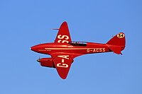
A biplane is a fixed-wing aircraft with two main wings stacked one above the other. The first powered, controlled aeroplane to fly, the Wright Flyer, used a biplane wing arrangement, as did many aircraft in the early years of aviation. While a biplane wing structure has a structural advantage over a monoplane, it produces more drag than a monoplane wing. Improved structural techniques, better materials and higher speeds made the biplane configuration obsolete for most purposes by the late 1930s.

<span class="mw-page-title-main">Monoplane</span> Fixed-wing aircraft with a single main wing plane

A monoplane is a fixed-wing aircraft configuration with a single mainplane, in contrast to a biplane or other types of multiplanes, which have multiple planes.

<span class="mw-page-title-main">Truss</span> Rigid structure that consists of two-force members only

A truss is an assembly of members such as beams, connected by nodes, that creates a rigid structure.

A biosensor is an analytical device, used for the detection of a chemical substance, that combines a biological component with a physicochemical detector. The sensitive biological element, e.g. tissue, microorganisms, organelles, cell receptors, enzymes, antibodies, nucleic acids, etc., is a biologically derived material or biomimetic component that interacts with, binds with, or recognizes the analyte under study. The biologically sensitive elements can also be created by biological engineering. The transducer or the detector element, which transforms one signal into another one, works in a physicochemical way: optical, piezoelectric, electrochemical, electrochemiluminescence etc., resulting from the interaction of the analyte with the biological element, to easily measure and quantify. The biosensor reader device connects with the associated electronics or signal processors that are primarily responsible for the display of the results in a user-friendly way. This sometimes accounts for the most expensive part of the sensor device, however it is possible to generate a user friendly display that includes transducer and sensitive element. The readers are usually custom-designed and manufactured to suit the different working principles of biosensors.

<span class="mw-page-title-main">Beam (structure)</span> Structural element capable of withstanding loads by resisting bending

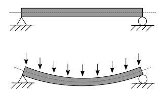
A beam is a structural element that primarily resists loads applied laterally across the beam's axis. Its mode of deflection is primarily by bending, as loads produce reaction forces at the beam's support points and internal bending moments, shear, stresses, strains, and deflections. Beams are characterized by their manner of support, profile, equilibrium conditions, length, and material.

<span class="mw-page-title-main">Cantilever bridge</span> Bridge built using cantilevers

A cantilever bridge is a bridge built using structures that project horizontally into space, supported on only one end. For small footbridges, the cantilevers may be simple beams; however, large cantilever bridges designed to handle road or rail traffic use trusses built from structural steel, or box girders built from prestressed concrete.

<span class="mw-page-title-main">Surface plasmon resonance</span> Physical phenomenon of electron resonance

Surface plasmon resonance (SPR) is a phenomenon that occurs where electrons in a thin metal sheet become excited by light that is directed to the sheet with a particular angle of incidence, and then travel parallel to the sheet. Assuming a constant light source wavelength and that the metal sheet is thin, the angle of incidence that triggers SPR is related to the refractive index of the material and even a small change in the refractive index will cause SPR to not be observed. This makes SPR a possible technique for detecting particular substances (analytes) and SPR biosensors have been developed to detect various important biomarkers.

<span class="mw-page-title-main">Spar (aeronautics)</span> Main structural member of the wing of an aircraft

In a fixed-wing aircraft, the spar is often the main structural member of the wing, running spanwise at right angles to the fuselage. The spar carries flight loads and the weight of the wings while on the ground. Other structural and forming members such as ribs may be attached to the spar or spars, with stressed skin construction also sharing the loads where it is used. There may be more than one spar in a wing or none at all. Where a single spar carries most of the force, it is known as the main spar.

<span class="mw-page-title-main">Stressed skin</span> Type of rigid construction

In mechanical engineering, stressed skin is a rigid construction in which the skin or covering takes a portion of the structural load, intermediate between monocoque, in which the skin assumes all or most of the load, and a rigid frame, which has a non-loaded covering. Typically, the main frame has a rectangular structure and is triangulated by the covering; a stressed skin structure has localized compression-taking elements and distributed tension-taking elements (skin).

<span class="mw-page-title-main">Girder bridge</span> Bridge built of girders placed on bridge abutments and foundation piers

A girder bridge is a bridge that uses girders as the means of supporting its deck. The two most common types of modern steel girder bridges are plate and box.

This is an alphabetical list of articles pertaining specifically to structural engineering. For a broad overview of engineering, please see List of engineering topics. For biographies please see List of engineers.

<span class="mw-page-title-main">Howe truss</span>

A Howe truss is a truss bridge consisting of chords, verticals, and diagonals whose vertical members are in tension and whose diagonal members are in compression. The Howe truss was invented by William Howe in 1840, and was widely used as a bridge in the mid to late 1800s.

<span class="mw-page-title-main">Fokker V.1</span> Type of aircraft

The Fokker V.1 was a small German sesquiplane experimental fighter prototype built in 1916 by the Fokker-Flugzeugwerke. Sporting a parasol wing, it was the first Fokker aircraft purportedly designed by Reinhold Platz—the respective roles played by Fokker himself, Platz, and possibly others in the conceptual design of Fokker airplanes are a matter of dispute among historians—and was an early experiment in cantilever wing construction, eliminating the bracing wires typical of aircraft design at the time, something that had already been achieved with metal materials in Hugo Junkers' own pioneering Junkers J 1 in 1915.

<span class="mw-page-title-main">Junkers J 1</span> Type of aircraft

The Junkers J 1, nicknamed the Blechesel, was an experimental monoplane aircraft developed by Junkers. It was the first all-metal aircraft in the world. Manufactured early on in the First World War, an era in which aircraft designers relied largely on fabric-covered wooden structures braced with wires, the J 1 was a revolutionary development in aircraft design, making extensive use of metal in its structure as had already been done and in its outer surface.

<span class="mw-page-title-main">Bio-MEMS</span>

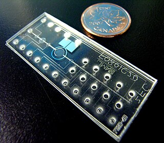
Bio-MEMS is an abbreviation for biomedical microelectromechanical systems. Bio-MEMS have considerable overlap, and is sometimes considered synonymous, with lab-on-a-chip (LOC) and micro total analysis systems (μTAS). Bio-MEMS is typically more focused on mechanical parts and microfabrication technologies made suitable for biological applications. On the other hand, lab-on-a-chip is concerned with miniaturization and integration of laboratory processes and experiments into single chips. In this definition, lab-on-a-chip devices do not strictly have biological applications, although most do or are amenable to be adapted for biological purposes. Similarly, micro total analysis systems may not have biological applications in mind, and are usually dedicated to chemical analysis. A broad definition for bio-MEMS can be used to refer to the science and technology of operating at the microscale for biological and biomedical applications, which may or may not include any electronic or mechanical functions. The interdisciplinary nature of bio-MEMS combines material sciences, clinical sciences, medicine, surgery, electrical engineering, mechanical engineering, optical engineering, chemical engineering, and biomedical engineering. Some of its major applications include genomics, proteomics, molecular diagnostics, point-of-care diagnostics, tissue engineering, single cell analysis and implantable microdevices.

The wafer bond characterization is based on different methods and tests. Considered a high importance of the wafer are the successful bonded wafers without flaws. Those flaws can be caused by void formation in the interface due to unevenness or impurities. The bond connection is characterized for wafer bond development or quality assessment of fabricated wafers and sensors.

<span class="mw-page-title-main">MEMS magnetic field sensor</span>

A MEMSmagnetic field sensor is a small-scale microelectromechanical systems (MEMS) device for detecting and measuring magnetic fields (Magnetometer). Many of these operate by detecting effects of the Lorentz force: a change in voltage or resonant frequency may be measured electronically, or a mechanical displacement may be measured optically. Compensation for temperature effects is necessary. Its use as a miniaturized compass may be one such simple example application.

<span class="mw-page-title-main">Non-contact atomic force microscopy</span>

Non-contact atomic force microscopy (nc-AFM), also known as dynamic force microscopy (DFM), is a mode of atomic force microscopy, which itself is a type of scanning probe microscopy. In nc-AFM a sharp probe is moved close to the surface under study, the probe is then raster scanned across the surface, the image is then constructed from the force interactions during the scan. The probe is connected to a resonator, usually a silicon cantilever or a quartz crystal resonator. During measurements the sensor is driven so that it oscillates. The force interactions are measured either by measuring the change in amplitude of the oscillation at a constant frequency just off resonance or by measuring the change in resonant frequency directly using a feedback circuit to always drive the sensor on resonance.

In aeronautics, bracing comprises additional structural members which stiffen the functional airframe to give it rigidity and strength under load. Bracing may be applied both internally and externally, and may take the form of struts, which act in compression or tension as the need arises, and/or wires, which act only in tension.

References

  1. Hool, George A.; Johnson, Nathan Clarke (1920). "Elements of Structural Theory - Definitions". Handbook of Building Construction (Google Books). Vol. 1 (1st ed.). New York: McGraw-Hill. p. 2. Retrieved 2008-10-01. A cantilever beam is a beam having one end rigidly fixed and the other end free.
  2. "GMI Construction wins £5.5M Design and Build Contract for Leeds United Football Club's Elland Road East Stand". Construction News. 6 February 1992. Retrieved 24 September 2012.
  3. IStructE The Structural Engineer Volume 77/No 21, 2 November 1999. James's Park a redevelopment challenge
  4. highbeam.com; The Architects' Journal. Existing stadiums: St James' Park, Newcastle. 1 July 2005
  5. Stevens, James Hay; The Shape of the Aeroplane, Hutchinson, 1953. pp.78 ff.
  6. Davy, M.J.B.; Aeronautics – Heavier-Than-Air Aircraft, Part I, Historical Survey, Revised edition, Science Museum/HMSO, December 1949. p.57.
  7. ELECTROMECHANICAL MONOLITHIC RESONATOR, US Pat.3417249 - Filed April 29, 1966
  8. R.J. Wilfinger, P. H. Bardell and D. S. Chhabra: The resonistor a frequency selective device utilizing the mechanical resonance of a silicon substrate, IBM J. 12, 113–118 (1968)
  9. P. M. Kosaka, J. Tamayo, J. J. Ruiz, S. Puertas, E. Polo, V. Grazu, J. M. de la Fuente and M. Calleja: Tackling reproducibility in microcantilever biosensors: a statistical approach for sensitive and specific end-point detection of immunoreactions, Analyst 138, 863–872 (2013)
  10. A. R. Salmon, M. J. Capener, J. J. Baumberg and S. R. Elliott: Rapid microcantilever-thickness determination by optical interferometry, Measurement Science and Technology 25, 015202 (2014)
  11. Patrick C. Fletcher; Y. Xu; P. Gopinath; J. Williams; B. W. Alphenaar; R. D. Bradshaw; Robert S. Keynton (2008). Piezoresistive Geometry for Maximizing Microcantilever Array Sensitivity. IEEE Sensors.
  12. Bănică, Florinel-Gabriel (2012). Chemical Sensors and Biosensors:Fundamentals and Applications. Chichester, UK: John Wiley & Sons. p. 576. ISBN   978-1-118-35423-0.
  13. Noyce, Steven G.; Vanfleet, Richard R.; Craighead, Harold G.; Davis, Robert C. (1999-02-22). "High surface-area carbon microcantilevers". Nanoscale Advances. 1 (3): 1148–1154. doi: 10.1039/C8NA00101D . PMC   9418787 . PMID   36133213.
  14. Zhao, Yue; Gosai, Agnivo; Shrotriya, Pranav (1 December 2019). "Effect of Receptor Attachment on Sensitivity of Label Free Microcantilever Based Biosensor Using Malachite Green Aptamer". Sensors and Actuators B: Chemical. 300. doi: 10.1016/j.snb.2019.126963 .

Sources