Last updated Great Western locomotives with their distinctive copper-rimmed chimneysAn American 4-4-0, with a large spark-arresting chimney
The chimney (smokestack or stack in American and Canadian English) is the part of a steam locomotive through which smoke leaves the boiler. As well, steam locomotive exhaust systems typically vent cylinder steam exhaust through the chimney, to enhance the draught through the boiler. Chimneys are designed to carry the exhaust steam and smoke clear of the driver's line of sight while remaining short enough to clear overhead structures. Some chimneys included apparatus to suppress the dispersal of sparks.
The chimney was usually located at the leading end of the locomotive, above the smokebox, furthest away from the driver's cab and firebox. The earliest locomotive chimneys were typically tall enough to sustain temperature-induced density difference draught through a fire-tube boiler while the locomotive was stationary. However, following the example of Richard Trevithick's first locomotive in 1804, most designs diverted steam cylinder exhaust upward through the chimney to create a vacuum in the smokebox, thereby accelerating airflow through the firebox while the locomotive was in motion.[1]
High chimneys on locomotives with low footplates had the additional advantage of keeping smoke and condensing steam above the engine driver's field of vision. Grade limitations on railways through hilly terrain required tunnels and overhead bridges, which imposed a loading gauge limiting the height of chimneys. Increasing the velocity of steam exhaust tended to both accelerate airflow through the firebox and lift the smoke higher above the top of the chimney. By the 1830s, steam exhaust was directed through a contracted nozzle called a blastpipe, so as to achieve the desired velocity through the chimney. Pressure drop through the blastpipe nozzle was subtracted from the boiler pressure available to the steam pistons. Robert Stephenson estimated some locomotives lost half their power through blastpipe back pressure.[2]
As developments in boiler design led to improvements in heat transfer efficiency, blast pipe diameters increased to reduce back pressure, and blastpipes became shorter, discharging below the chimney rather than within it. Ross Winans placed conical "petticoat pipes" above blastpipes about 1848[2] to form the convergent portion of a venturi tube, with the chimney forming the divergent portion.[3] Improved understanding of compressible flow encouraged more sophisticated blastpipe and venturi chimney designs. George Jackson Churchward, working at Swindon on the Great Western Railway, formulated a simple equation for calculating the ideal dimensions for chimneys, which worked well for the early years of the 20th century, but become outdated as engine power increased. André Chapelon in France continued to work on chimney dimensions and studied them, in conjunction with blastpipe dimensions, as a complete exhaust system. That led to his famous Kylchap system, which was fitted to many classes of locomotives worldwide. Even after the use of commercial steam locomotives in most of the developed world came to an end, the Argentinean engineer Livio Dante Porta continued to work on developing steam locomotive exhaust systems, including refining equations to give better chimney dimensions.
Spark arrestors
Locomotives built in Great Britain, where coke was the most common fuel, often used chimneys of cast iron, because they lasted longer than chimneys fabricated from sheet metal. Early North American locomotives often used wood fuel, which resulted in large numbers of glowing embers being carried through the boiler from the firebox and blasted out of the chimney by the high-velocity exhaust steam.[4] To reduce the number of fires started by escaped embers, spark arrestors became a common feature of wood-burning locomotive chimneys. The difficulty of casting complex spark arrestors encouraged fabrication of sheet metal chimneys for wood-burning locomotives.[5]
Fifty-seven of over one thousand locomotive spark arrestors patented in the United States, 1857
Early spark arrestors were simply iron wire screens installed within the stack. However, the screen reduced the rate at which smoke and steam could escape from the boiler. As well, embers caught by the screen further reduced available space for the passage of steam, and smoke and heat generated by the burning embers rapidly melted the wire screen. Chimney top diameters were enlarged to increase screen surface area and reduce smoke velocity through the screen so that embers could fall away from the screen into collection hoppers. In response to an 1857 patent infringement claim, Baldwin Locomotive Works compiled a diagram illustrating 57 different spark arresting chimney designs.[4]
The most popular design was a bonnet chimney. The bonnet was a funnel-shaped sheet metal cone fitted over a conventional cylindrical chimney. The lower, small-diameter portion of the cone served as a collection hopper for falling embers. The upper portion of the cone concealed an inner cone at the top of the cylindrical chimney, which deflected escaping steam, smoke and embers outward against the inner walls of the outer cone. The heavier embers were expected to fall into the hopper below, while the lighter steam and smoke passed upward through a wire screen over the upper, large-diameter end of the outer cone. Deflection of the embers typically limited the life of the screen to three or four weeks. Some of those chimneys included provision for dropping collected embers into a portion of the smokebox called the subtreasury. Sophisticated designs, such as the Radley & Hunter, incorporated various centrifugal separation baffles into the bonnet. As coal replaced wood fuel, the bonnet was reduced into a simple diamond chimney, housing the inner deflecting cone, with or without the upper wire screen, but without any collection hopper.[4]
Aesthetics
The bonnet chimney became one of the most distinctive features 19th-century American locomotives. That, along with a large rectangular oil headlamp, gave them an air of grandeur.[4] Many designers or railway companies had their own distinctive style, such as the William Adams' "Stovepipe" chimney on the 19th century London and South Western Railway, or the copper-capped chimneys on the Great Western Railway.
As locomotive boilers grew larger, the space available for chimneys was reduced, because they still had to fit within the same loading gauge. That reduced the effectiveness of the chimney in keeping the exhaust gases away from the driver's line of sight and, as a result, locomotives had to be fitted with devices such as smoke deflectors.
Stephenson's Rocket is an early steam locomotive of 0-2-2 wheel arrangement. It was built for and won the Rainhill Trials of the Liverpool and Manchester Railway (L&MR), held in October 1829 to show that improved locomotives would be more efficient than stationary steam engines.
A steam locomotive is a locomotive that provides the force to move itself and other vehicles by means of the expansion of steam. It is fuelled by burning combustible material to heat water in the locomotive's boiler to the point where it becomes gaseous and its volume increases 1,700 times. Functionally, it is a steam engine on wheels.
Main components found on a typical steam locomotive include:
An injector is a system of ducting and nozzles used to direct the flow of a high-pressure fluid in such a way that a lower pressure fluid is entrained in the jet and carried through a duct to a region of higher pressure. It is a fluid-dynamic pump with no moving parts except a valve to control inlet flow.
A fire-tube boiler is a type of boiler invented in 1828 by Mark Seguin, in which hot gases pass from a fire through one or more tubes running through a sealed container of water. The heat of the gases is transferred through the walls of the tubes by thermal conduction, heating the water and ultimately creating steam.
The LSWR N15 class was a British 2–cylinder 4-6-0 express passenger steam locomotive designed by Robert Urie. The class has a complex build history spanning three sub-classes and eight years of construction from 1918 to 1927. The first batch of the class was constructed for the London and South Western Railway (LSWR), where they hauled heavy express passenger trains to the south coast ports and further west to Exeter. After the Lord Nelsons, they were the second biggest 4-6-0 passenger locomotives on the Southern Railway. They could reach speeds of up to 90 mph (145 km/h).
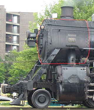
A smokebox is one of the major basic parts of a steam locomotive exhaust system. Smoke and hot gases pass from the firebox through tubes where they pass heat to the surrounding water in the boiler. The smoke then enters the smokebox, and is exhausted to the atmosphere through the chimney. Early locomotives had no smokebox and relied on a long chimney to provide natural draught for the fire but smokeboxes were soon included in the design for two specific reasons. Firstly and most importantly, the blast of exhaust steam from the cylinders, when directed upwards through an airtight smokebox with an appropriate design of exhaust nozzle, effectively draws hot gases through the boiler tubes and flues and, consequently, fresh combustion air into the firebox. Secondly, the smokebox provides a convenient collection point for ash and cinders ("char") drawn through the boiler tubes, which can be easily cleaned out at the end of a working day. Without a smokebox, all char must pass up the chimney or it will collect in the tubes and flues themselves, gradually blocking them.
The London and North Eastern Railway (LNER) Peppercorn Class A2 is a class of steam locomotive designed for express passenger work by Arthur Peppercorn, the chief designer of the LNER after Edward Thompson. All save the first of the 15 built were constructed under British Railways after nationalisation in 1948. Only one example is preserved.
The blastpipe is part of the exhaust system of a steam locomotive that discharges exhaust steam from the cylinders into the smokebox beneath the chimney in order to increase the draught through the fire.
The London, Midland and Scottish Railway (LMS) 2 and 2A boilered 4-6-0 locomotives were express passenger 4-6-0 steam locomotives. In 1935, William Stanier, Chief Mechanical Engineer of the LMS, ordered the rebuilding of the unique experimental high pressure compound locomotive 6399 Fury. The Schmidt-Henschel boiler was replaced with a tapered boiler, with a drumhead smokebox, designated type 2. The type 2 boiler had a tube surface of 1,669 square feet, formed by tubes 2⅛ inches in diameter and 14 feet 3 inches long. It was fitted with a 28 row superheater with 360 square feet of heating surface. The superheater elements, 1⅛ inch in diameter, were fitted into flue tubes 5⅛ inches diameter.
A shell or flued boiler is an early and relatively simple form of boiler used to make steam, usually for the purpose of driving a steam engine. The design marked a transitional stage in boiler development, between the early haystack boilers and the later multi-tube fire-tube boilers. A flued boiler is characterized by a large cylindrical boiler shell forming a tank of water, traversed by one or more large flues containing the furnace. These boilers appeared around the start of the 19th century and some forms remain in service today. Although mostly used for static steam plants, some were used in early steam vehicles, railway locomotives and ships.
British Railways Standard Class 9F steam locomotives Nos 92020-9 were experimentally built with Franco-Crosti boilers, thus forming a subclass. All ten were built in 1955 at Crewe Works.
Boilers for generating steam or hot water have been designed in countless shapes, sizes and configurations. An extensive terminology has evolved to describe their common features. This glossary provides definitions for these terms.
A transverse boiler is a boiler used to generate steam to power a vehicle. Unlike other boilers, its external drum is mounted transversely across the vehicle.
The steam locomotive exhaust system consists of those parts of a steam locomotive which together discharge exhaust steam from the cylinders in order to increase the draught through the fire. It usually consists of the blastpipe, smokebox, and chimney, although later designs also include second and third stage nozzles.
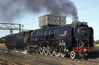
The South African Railways Class 25 4-8-4 of 1953 was a condensing steam locomotive.
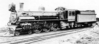
The South African Railways Class 10B 4-6-2 of 1910 was a steam locomotive from the pre-Union era in Transvaal.
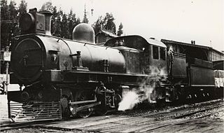
The South African Railways Class KM 0-6-0+0-6-0 of 1904 was an articulated steam locomotive from the pre-Union era in Transvaal Colony.
The South African Railways Class MG 2-6-6-2 of 1911 was a steam locomotive from the pre-Union era in Transvaal.
A double chimney is a form of chimney for a steam locomotive, where the conventional single opening is duplicated, together with the blastpipe beneath it. Although the internal openings form two circles, the outside appearance usually forms a single elongated oval.
This page is based on this Wikipedia article Text is available under the CC BY-SA 4.0 license; additional terms may apply. Images, videos and audio are available under their respective licenses.