Gresley conjugated valve gear

Last updated

LNER Class V2 4771 Green Arrow. Note Gresley conjugated valve gear located ahead of the piston valves, driven from the valve spindles GA at SVR.JPG
LNER Class V2 4771 Green Arrow. Note Gresley conjugated valve gear located ahead of the piston valves, driven from the valve spindles

The Gresley conjugated valve gear is a valve gear for steam locomotives designed by Sir Nigel Gresley, chief mechanical engineer of the LNER, assisted by Harold Holcroft. It enables a three-cylinder locomotive to operate with only the two sets of valve gear for the outside cylinders, and derives the valve motion for the inside cylinder from them by means of levers (the "2 to 1 lever" and "equal lever"). [1] The gear is sometimes known as the Gresley-Holcroft gear, acknowledging Holcroft's major contributions to its development.

Contents

Operation

New South Wales Government Railways D57 class 4-8-2, with Gresley conjugated gear visible at front below the smokebox. The longer 2 to 1 Lever is located on the right side of the locomotive, and the shorter Equal Lever on the left side. Arhs 57 class.jpg
New South Wales Government Railways D57 class 4-8-2, with Gresley conjugated gear visible at front below the smokebox. The longer 2 to 1 Lever is located on the right side of the locomotive, and the shorter Equal Lever on the left side.

The Gresley conjugated gear is effectively an adding machine, where the position of the valve for the inside cylinder is the sum of the positions of the two outside cylinders, but reversed in direction. It can also be thought of as a rocking lever between one outside cylinder and the inside cylinder, as is common on 4-cylinder steam locomotives, but with the pivot point being moved back and forth by a lever from the other outside cylinder.

If we approximate the motion of each valve by a sine wave if we say the position of a valve in its back-and-forth travel is exactly proportional to the sine of the "driver angle", once we have set the zero point of driver angle at the position it needs to be for that valve then the mathematics is simple. The position of the valve that is pinned to the long end of the 2-to-1 lever is , while the positions of the other two valves are supposed to be and . The position of the short end of the 2-to-1 lever is  —which, it turns out, is midway between and for any value of . So a 1-to-1 lever pivoted on the short arm of the 2-to-1 lever will do the trick.[ citation needed ]

Crank angles

Locomotives with Gresley valve gear must have the three pistons operating at precisely 120 degree intervals. (Different spacings could be accommodated by different lever proportions, if there were any advantage to a spacing other than 120-120-120.) In order for the inside connecting rod to clear the leading coupled axle, the inside cylinder of a locomotive with Gresley valve gear is typically positioned higher than the outside cylinders and angled downward. [2] To maintain a smooth flow of torque, the crank angles are offset from equal 120 degree spacing to compensate for the angle of the inside cylinder (e.g. 120/113/127 degrees). The resultant timing of the blast from steam exiting the cylinders gives these three-cylinder locomotives a regular exhaust beat.

Problems

There were a number of issues with the Gresley gear. Because the conjugation apparatus was mounted at the opposite end of the valve spindles from the valve gear, as the valve spindles lengthened with the heat of steam in the cylinders the valve timing would be affected, and the gear would need to be removed before it was possible to remove valves for maintenance. [3] However, the B17 Class "Footballer"/"Sandringham" 4-6-0s avoided this particular problem by being designed with the conjugated gear behind, rather than in front of, the cylinders. [4] The main difficulty with this valve gear was that at high speeds, inertial forces caused the long conjugating lever to bend or "whip". [5] This had the effect of causing the middle cylinder to operate at a longer cutoff than the outer cylinders, therefore producing a disproportionate share of the total power output, leading to increased wear of the middle big end. Sustained high speed running could sometimes cause the big end to wear rapidly enough that the increased travel afforded to the middle piston by the increased play in the bearing was enough to knock the ends off the middle cylinder. This happened during the 113 miles per hour (200 km/h) run of "Silver Fox". [6] Although the problem could be contained in a peacetime environment with regular maintenance and inspections, it proved to be poorly suited to the rigors of heavy running and low maintenance levels of World War II. This gave rise to big-end problems on the centre cylinder connecting rod on the famous A4 class of streamlined Pacifics and many of these locomotives were fitted with a reduced diameter piston and had the inside cylinder sleeved down as a temporary measure. LNER Class A4 4468 Mallard suffered centre cylinder big-end damage (indicated to the driver by the fracture of a "stink bomb" attached to the bearing, which fractures during overheating of the white metal) during its world record run and was forced to limp back to its depot for repairs afterwards. Gresley's successor at the LNER, Edward Thompson, was critical of this particular valve gear. [7] As well as introducing new two-cylinder designs, he set about rebuilding Gresley locomotives with separate sets of Walschaerts valve gear for each cylinder. [8] Under later British Railways ownership, the application of former Great Western Railway workshop practices for precise alignment of the valve gear and in the manufacture and lubrication of the inside big end bearing effectively solved the problems.

North America, Australia and New Zealand

The third cylinder and Gresley gear are visible below the smokebox of this 4-12-2. UP 9000.jpg
The third cylinder and Gresley gear are visible below the smokebox of this 4-12-2.

Gresley conjugated valve gear was used by the American Locomotive Company under license for the 4-12-2 locomotives, the Union Pacific 9000 class, built for the Union Pacific Railroad between 1926 and 1930. These were the largest locomotives to use this valve gear. It was also used in Australia for the Victorian Railways S class 4-6-2 of 1928 [9] and New South Wales Government Railways D57 class 4-8-2 of 1929. [10]

As in the UK, the mechanism was not without its problems. Some of the Union Pacific 9000 class locomotives were converted to a "double Walschaerts" valve gear, while later examples were built with roller bearings for the moving parts of the Gresley mechanism. In Australia, the VR S class Pacifics avoided many of the middle cylinder problems that beset Gresley by placing a 'set' in the axle of the leading driving wheels, thus allowing all three cylinders to be in the same horizontal plane. Later VR and NSWGR three cylinder locomotive designs used alternative mechanisms to the Gresley system in an effort to overcome its high maintenance overhead. [11] [12] The Victorian Railways H class of 1941 was fitted with a German Henschel und Sohn conjugated valve gear mechanism which was judged to be superior to the Gresley system, [13] while in New South Wales the D58 class of 1950 utilised a rack and pinion system which while in theory an improvement over the Gresley system, proved in practice to be even more problematic. [11]

Gresley valve gear was used on the NZR G class Beyer-Garrett six-cylinder locomotives supplied to the New Zealand Railways in 1928. The manufacturer Beyer Peacock advised against the three/six-cylinder option with Gresley gear but it was required by G S Lynde the NZR CME. These three articulated locomotives were not a success, and they were rebuilt into six "Pacific" locomotives.

See also

Related Research Articles

<span class="mw-page-title-main">LNER Class A4</span> Class of locomotives designed by Sir Nigel Gresley

The LNER Class A4 is a class of streamlined 4-6-2 steam locomotive designed by Nigel Gresley for the London and North Eastern Railway in 1935. Their streamlined design gave them high-speed capability as well as making them instantly recognisable, and one of the class, 4468 Mallard, holds the record as the world's fastest steam locomotive. Thirty-five of the class were built to haul express passenger trains on the East Coast Main Line route from London Kings Cross via York to Newcastle, and later via Newcastle to Edinburgh, Scotland. They remained in service on the East Coast Main Line until the early 1960s when they were replaced by Deltic diesel locomotives; they themselves proving to be worthy successors to the A4s. Several A4s saw out their remaining days until 1966 in Scotland, particularly on the Aberdeen – Glasgow express trains, for which they were used to improve the timing from 3.5 to 3 hours.

<span class="mw-page-title-main">Nigel Gresley</span> British engineer

Sir Herbert Nigel Gresley was a British railway engineer. He was one of Britain's most famous steam locomotive engineers, who rose to become Chief Mechanical Engineer (CME) of the London and North Eastern Railway (LNER). He was the designer of some of the most famous steam locomotives in Britain, including the LNER Class A1 and LNER Class A4 4-6-2 Pacific engines. An A1 Pacific, Flying Scotsman, was the first steam locomotive officially recorded over 100 mph in passenger service, and an A4, number 4468 Mallard, still holds the record for being the fastest steam locomotive in the world (126 mph).

<span class="mw-page-title-main">Valve gear</span> Mechanism for controlling steam flow in a reciprocating steam engine.

The valve gear of a steam engine is the mechanism that operates the inlet and exhaust valves to admit steam into the cylinder and allow exhaust steam to escape, respectively, at the correct points in the cycle. It can also serve as a reversing gear. It is sometimes referred to as the "motion".

<span class="mw-page-title-main">Union Pacific 9000 Class</span> Steam locomotive class

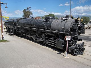
The Union Pacific Railroad 9000 Class was a class of 88 steam locomotives, built by ALCO for the Union Pacific between 1926 and 1930.

<span class="mw-page-title-main">LNER Class D49</span>

The London and North Eastern Railway (LNER) D49 Class is a class of 4-4-0 steam locomotives designed by Nigel Gresley. They were named after fox hunts and shires.

<span class="mw-page-title-main">LNER Gresley Classes A1 and A3</span> Class of 4-6-2 pacific locomotive designed by Sir Nigel Gresley

The London and North Eastern Railway LNER Gresley Classes A1 and A3 locomotives represented two distinct stages in the history of the British 4-6-2 "Pacific" steam locomotives designed by Nigel Gresley. They were designed for main line passenger services and later express passenger services, initially on the Great Northern Railway (GNR), a constituent company of the London and North Eastern Railway after the amalgamation of 1923, for which they became a standard design. The change in class designation to A3 reflected the fitting to the same chassis of a higher pressure boiler with a greater superheating surface and a small reduction in cylinder diameter, leading to an increase in locomotive weight. Eventually all of the A1 locomotives were rebuilt, most to A3 specifications, but no. 4470 was completely rebuilt as Class A1/1.

<span class="mw-page-title-main">NER Class S3</span>

The North Eastern Railway Class S3, classified B16 by the LNER, was a class of 4-6-0 steam locomotive designed for mixed traffic work. It was designed by Vincent Raven and introduced in 1920. The earlier members of this class were fitted with Westinghouse Brakes - all of this equipment was removed during the 1930s.

Edward Thompson was an English railway engineer, and was Chief Mechanical Engineer of the London and North Eastern Railway between 1941 and 1946. Edward Thompson was born at Marlborough, Wiltshire on 25 June 1881. He was the son of Francis Thompson, assistant master at Marlborough College. He was educated at Marlborough before taking the Mechanical Science Tripos at Pembroke College, Cambridge, earning a third class degree. Thompson entered the railway scene after education, contrasting that of his predecessor Nigel Gresley, who had also attended Marlborough after gaining practical experience as a pupil at Horwich Works.

<span class="mw-page-title-main">SR U1 class</span>

The SR U1 class were three-cylinder 2-6-0 ('mogul') steam locomotives designed by Richard Maunsell for passenger duties on the Southern Railway. The fifth member of the Maunsell "family" of standardised moguls and 2-6-4 locomotives, the U1 was the final development of the Maunsell mogul, and marked a continuation of the basic principles established by CME George Jackson Churchward for the GWR. Developed from Maunsell's previous SR U class design, the U1 class shared characteristics with Churchward's GWR 4300 Class.

<span class="mw-page-title-main">LNER Class P2</span> Class of 6 three-cylinder 2-8-2 locomotives

The London and North Eastern Railway Class P2 was a class of 2-8-2 steam locomotives designed by Sir Nigel Gresley for working heavy express trains over the harsh Edinburgh to Aberdeen Line. As they were to serve on Scottish expresses, they were given famous names from Scottish lore.

<span class="mw-page-title-main">LNER Thompson Class A1/1</span>

The LNER Class A1/1 consisted of a single 4-6-2 "Pacific" express passenger locomotive rebuilt in 1945 from an A1 class locomotive, by Edward Thompson. It was intended as the prototype of a new design of pacific locomotives improving the A4 design of Thompson's predecessor Sir Nigel Gresley. No further examples were built due to Thompson's retirement in 1946.

<span class="mw-page-title-main">Cylinder (locomotive)</span> Power-producing element of a steam locomotive

The cylinder is the power-producing element of the steam engine powering a steam locomotive. The cylinder is made pressure-tight with end covers and a piston; a valve distributes the steam to the ends of the cylinder. Cylinders were initially cast iron, but later made of steel. The cylinder casting includes other features such as valve ports and mounting feet. The last big American locomotives incorporated the cylinders as part of huge one-piece steel castings that were the main frame of the locomotive. Renewable wearing surfaces were needed inside the cylinders and provided by cast-iron bushings.

Henry Greenly (1876–1947) was amongst the foremost miniature railway engineers of the 20th century, remembered as a master of engineering design.

<span class="mw-page-title-main">SECR N1 class</span> Class of 6 three-cylinder 2-6-0 locomotives

The SECR N1 class was a type of 3-cylinder 2-6-0 ('mogul') steam locomotive designed by Richard Maunsell for mixed traffic duties, initially on the South Eastern and Chatham Railway (SECR), and later operated for the Southern Railway (SR). The N1 was a development of the basic principles established by the Great Western Railway's (GWR) Chief Mechanical Engineer (CME) George Jackson Churchward and by Maunsell's previous N class design.

<span class="mw-page-title-main">LNER Thompson Class A2/1</span>

The London and North Eastern Railway (LNER) Thompson Class A2/1 was a class of 4-6-2 steam locomotives built at Darlington locomotive works during 1944. They were originally ordered as Class V2 locomotives, as designed by Sir Nigel Gresley, but were revised during construction into a 4-6-2 'Pacific' arrangement under the instruction of Edward Thompson.

<span class="mw-page-title-main">LNER Thompson Class A2/2</span> British steam locomotive

The London and North Eastern Railway Class A2/2 was a class of six 4-6-2 steam locomotives rebuilt by Edward Thompson in 1943 and 1944 from his predecessor Sir Nigel Gresley's P2 Class of 2-8-2 express passenger locomotives. The rebuilds improved reliability and reduced maintenance, but also suffered from a variety of issues during service, and all were withdrawn and scrapped between 1959 and 1961.

Harold Holcroft was an English railway and mechanical engineer who worked for the Great Western Railway (GWR), the South Eastern and Chatham Railway (SECR) and the Southern Railway (SR).

<span class="mw-page-title-main">Holcroft valve gear</span>

The Holcroft valve gear was a type of conjugated valve gear designed and patented by Harold Holcroft and used on three-cylinder steam locomotives of the South Eastern & Chatham Railway (SECR). It bore many similarities to the Gresley conjugated valve gear, which it predated, as eventually used on all Gresley's three cylinder designs. It varied from the Gresley method of operation by using the combination lever assembly instead of the valve spindles to drive the middle cylinder of a three-cylinder design. This had operational advantages over Gresley's design, namely eliminating the problems of flexure, bush wear and the influence of heat in the valve spindles.

<span class="mw-page-title-main">GCR Class 9P</span>

GCR Class 9P was a design of four-cylinder steam locomotive of the 4-6-0 wheel arrangement built for hauling express passenger trains on the Great Central Railway in England. A total of six were built: one in 1917, and five in 1920. They were sometimes known as the Lord Faringdon class, from the name of the first one built.

References

  1. Restoration of Gresley A4 #60019 Bittern Archived 12 March 2007 at the Wayback Machine Diagram of Gresley and Walschaerts valve gear arrangement on LNER A4 locomotive - retrieved 4 October 2006 [ dead link ]
  2. Public Record Office Victoria photograph of cylinder castings for VR S class Archived 10 March 2007 at the Wayback Machine -retrieved 4 October 2006. Note incline of centre cylinder.
  3. "Locomotive Adventure" Harold Holcroft, Ian Allan. London
  4. "The Last Steam Locomotives of British Railways", Ransome-Wallis, P., Ian Allan, Shepperton, 1966
  5. Bill Harvey's 60 years in steam, Harvey, D.W. David & Charles. Newton Abbot, 1986
  6. Allen, CJ, "Two Million Miles of Train Travel", ISBN   0-7110-0298-3
  7. (LNER) Encyclopedia Edward Thompson page retrieved 1 October 2006
  8. (LNER) Encyclopedia A1/1 page retrieved 1 October 2006
  9. AHRS Railway Museum History: 1900 - 1950 Archived 27 September 2007 at the Wayback Machine retrieved 1 October 2006
  10. australiansteam.com NSW page retrieved 1 October 2006
  11. 1 2 Slee, David E. (January 2000). "D57 and D58 Classes - Design Differences and Power Comparisons". Australian Railway Historical Society Bulletin: 3–19.
  12. Oberg, Leon (2007). Locomotives of Australia 1854-2007. Rosenberg Publishing. p. 201. ISBN   978-1-877058-54-7.
  13. Lee, Robert (2007). The Railways of Victoria 1854-2004. Melbourne University Publishing Ltd. p. 165. ISBN   978-0-522-85134-2.