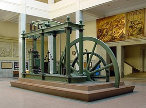
A late version of a Watt double-actingsteam engine, built by D. Napier & Son (London) in 1832, now in the lobby of the Superior Technical School of Industrial Engineers of the UPM (Madrid). Steam engines of this kind propelled the Industrial Revolution in Great Britain and the world.
The Watt steam engine design became synonymous with steam engines, and it was many years before significantly new designs began to replace the basic Watt design.
The first steam engines, introduced by Thomas Newcomen in 1712, were of the "atmospheric" design. At the end of the power stroke, the weight of the object being moved by the engine pulled the piston to the top of the cylinder as steam was introduced. Then the cylinder was cooled by a spray of water, which caused the steam to condense, forming a partial vacuum in the cylinder. Atmospheric pressure on the top of the piston pushed it down, lifting the work object. James Watt noticed that it required significant amounts of heat to warm the cylinder back up to the point where steam could enter the cylinder without immediately condensing. When the cylinder was warm enough that it became filled with steam the next power stroke could commence.
Watt realised that the heat needed to warm the cylinder could be saved by adding a separate condensing cylinder. After the power cylinder was filled with steam, a valve was opened to the secondary cylinder, allowing the steam to flow into it and be condensed, which drew the steam from the main cylinder causing the power stroke. The condensing cylinder was water cooled to keep the steam condensing. At the end of the power stroke, the valve was closed so the power cylinder could be filled with steam as the piston moved to the top. The result was the same cycle as Newcomen's design, but without any cooling of the power cylinder which was immediately ready for another stroke.
Watt worked on the design over a period of several years, introducing the condenser, and introducing improvements to practically every part of the design. Notably, Watt performed a lengthy series of trials on ways to seal the piston in the cylinder, which considerably reduced leakage during the power stroke, preventing power loss. All of these changes produced a more reliable design which used half as much coal to produce the same amount of power.[1]
The new design was introduced commercially in 1776, with the first example sold to the Carron Company ironworks. Watt continued working to improve the engine, and in 1781 introduced a system using a sun and planet gear to turn the linear motion of the engines into rotary motion. This made it useful not only in the original pumping role, but also as a direct replacement in roles where a water wheel would have been used previously. This was a key moment in the industrial revolution, since power sources could now be located anywhere instead of, as previously, needing a suitable water source and topography. Watt's partner Matthew Boulton began developing a multitude of machines that made use of this rotary power, developing the first modern industrialized factory, the Soho Foundry, which in turn produced new steam engine designs. Watt's early engines were like the original Newcomen designs in that they used low-pressure steam, and all of the power was produced by atmospheric pressure. When, in the early 1800s, other companies introduced high-pressure steam engines, Watt was reluctant to follow suit due to safety concerns.[2] Wanting to improve on the performance of his engines, Watt began considering the use of higher-pressure steam, as well as designs using multiple cylinders in both the double-acting concept and the multiple-expansion concept. These double-acting engines required the invention of the parallel motion, which allowed the piston rods of the individual cylinders to move in straight lines, keeping the piston true in the cylinder, while the walking beam end moved through an arc, somewhat analogous to a crosshead in later steam engines.
Introduction
In 1698, the English mechanical designer Thomas Savery invented a pumping appliance that used steam to draw water directly from a well by means of a vacuum created by condensing steam. The appliance was also proposed for draining mines, but it could only draw fluid up approximately 25 feet, meaning it had to be located within this distance of the mine floor being drained. As mines became deeper, this was often impractical. It also consumed a large amount of fuel compared with later engines.[3]
The solution to draining deep mines was found by Thomas Newcomen who developed an "atmospheric" engine that also worked on the vacuum principle. It employed a cylinder containing a movable piston connected by a chain to one end of a rocking beam that worked a mechanical lift pump from its opposite end. At the bottom of each stroke, steam was allowed to enter the cylinder below the piston. As the piston rose within the cylinder, drawn upward by a counterbalance, it drew in steam at atmospheric pressure. At the top of the stroke the steam valve was closed, and cold water was briefly injected into the cylinder as a means of cooling the steam. This water condensed the steam and created a partial vacuum below the piston. The atmospheric pressure outside the engine was then greater than the pressure within the cylinder, thereby pushing the piston into the cylinder. The piston, attached to a chain and in turn attached to one end of the "rocking beam", pulled down the end of the beam, lifting the opposite end of the beam. Hence, the pump deep in the mine attached to opposite end of the beam via ropes and chains was driven. The pump pushed, rather than pulled the column of water upward, hence it could lift water any distance. Once the piston was at the bottom, the cycle repeated.[3]
The Newcomen engine was more powerful than the Savery engine. For the first time water could be raised from a depth of over 300 feet. [4] The first example from 1712 was able to replace a team of 500 horses that had been used to pump out the mine. Seventy-five Newcomen pumping engines were installed at mines in Britain, France, Holland, Sweden and Russia. In the next fifty years only a few small changes were made to the engine design. It was a great advancement.
While Newcomen engines brought practical benefits, they were inefficient in terms of the use of energy to power them. The system of alternately sending jets of steam, then cold water into the cylinder meant that the walls of the cylinder were alternately heated, then cooled with each stroke. Each charge of steam introduced would continue condensing until the cylinder approached working temperature once again. So at each stroke part of the potential of the steam was lost.
Separate condenser
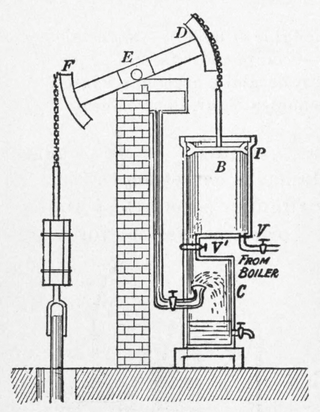
The major components of a Watt pumping engine
In 1763, James Watt was working as instrument maker at the University of Glasgow when he was assigned the job of repairing a model Newcomen engine and noted how inefficient it was.[5]
In 1765, Watt conceived the idea of equipping the engine with a separate condensation chamber, which he called a "condenser". Because the condenser and the working cylinder were separate, condensation occurred without significant loss of heat from the cylinder. The condenser remained cold and below atmospheric pressure at all times, while the cylinder remained hot at all times.
Steam was drawn from the boiler to the cylinder under the piston. When the piston reached the top of the cylinder, the steam inlet valve closed and the valve controlling the passage to the condenser opened. The condenser being at a lower pressure, drew the steam from the cylinder into the condenser where it cooled and condensed from water vapour to liquid water, maintaining a partial vacuum in the condenser that was communicated to the space of the cylinder by the connecting passage. External atmospheric pressure then pushed the piston down the cylinder.
The separation of the cylinder and condenser eliminated the loss of heat that occurred when steam was condensed in the working cylinder of a Newcomen engine. This gave the Watt engine greater efficiency than the Newcomen engine, reducing the amount of coal consumed while doing the same amount of work as a Newcomen engine.
In Watt's design, the cold water was injected only into the condensation chamber. This type of condenser is known as a jet condenser. The condenser is located in a cold water bath below the cylinder. The volume of water entering the condenser as spray absorbed the latent heat of the steam, and was determined as seven times the volume of the condensed steam. The condensate and the injected water was then removed by the air pump, and the surrounding cold water served to absorb the remaining thermal energy to retain a condenser temperature of 30°C to 45°C and the equivalent pressure of 0.04 to 0.1 bar [6]
At each stroke the warm condensate was drawn off from the condenser and sent to a hot well by a vacuum pump, which also helped to evacuate the steam from under the power cylinder. The still-warm condensate was recycled as feedwater for the boiler.
Watt's next improvement to the Newcomen design was to seal the top of the cylinder and surround the cylinder with a jacket. Steam was passed through the jacket before being admitted below the piston, keeping the piston and cylinder warm to prevent condensation within it. The second improvement was the utilisation of steam expansion against the vacuum on the other side of the piston. The steam supply was cut during the stroke, and the steam expanded against the vacuum on the other side. This increased the efficiency of the engine, but also created a variable torque on the shaft which was undesirable for many applications, in particular pumping. Watt therefore limited the expansion to a ratio of 1:2 (i.e. the steam supply was cut at half stroke). This increased the theoretical efficiency from 6.4% to 10.6%, with only a small variation in piston pressure.[6] Watt did not use high pressure steam because of safety concerns.[2]:85
These improvements led to the fully developed version of 1776 that actually went into production.[7]
The separate condenser showed dramatic potential for improvements on the Newcomen engine but Watt was still discouraged by seemingly insurmountable problems before a marketable engine could be perfected. It was only after entering into partnership with Matthew Boulton that such became reality. Watt told Boulton about his ideas on improving the engine, and Boulton, an avid entrepreneur, agreed to fund development of a test engine at Soho, near Birmingham. At last Watt had access to facilities and the practical experience of craftsmen who were soon able to get the first engine working. As fully developed, it used about 75% less fuel than a similar Newcomen one.
Watt had tried unsuccessfully for several years to obtain an accurately bored cylinder for his steam engines, and was forced to use hammered iron, which was out of round and caused leakage past the piston. Joseph Wickham Roe stated in 1916: "When [John] Smeaton saw the first engine he reported to the Society of Engineers that 'Neither the tools nor the workmen existed who could manufacture such a complex machine with sufficient precision'".[9]
In 1774, John Wilkinson invented a boring machine in which the shaft that held the cutting tool was supported on both ends and extended through the cylinder, unlike the cantilevered borers then in use. Boulton wrote in 1776 that "Mr. Wilkinson has bored us several cylinders almost without error; that of 50 inches diameter, which we have put up at Tipton, does not err on the thickness of an old shilling in any part".[9]
Boulton and Watt's practice was to help mine-owners and other customers to build engines, supplying men to erect them and some specialised parts. However, their main profit from their patent was derived from charging a licence fee to the engine owners, based on the cost of the fuel they saved. The greater fuel efficiency of their engines meant that they were most attractive in areas where fuel was expensive, particularly Cornwall, for which three engines were ordered in 1777, for the Wheal Busy, Ting Tang, and Chacewater mines.[10]
The first Watt engines were atmospheric pressure engines, like the Newcomen engine but with the condensation taking place separate from the cylinder. Driving the engines using both low pressure steam and a partial vacuum raised the possibility of reciprocating engine development.[11] An arrangement of valves could alternately admit low pressure steam to the cylinder and then connect with the condenser. Consequently, the direction of the power stroke might be reversed, making it easier to obtain rotary motion. Additional benefits of the double acting engine were increased efficiency, higher speed (greater power) and more regular motion.
Before the development of the double acting piston, the linkage to the beam and the piston rod had been by means of a chain, which meant that power could only be applied in one direction, by pulling. This was effective in engines that were used for pumping water, but the double action of the piston meant that it could push as well as pull. This was not possible as long as the beam and the rod were connected by a chain. Furthermore, it was not possible to connect the piston rod of the sealed cylinder directly to the beam, because while the rod moved vertically in a straight line, the beam was pivoted at its centre, with each side inscribing an arc. To bridge the conflicting actions of the beam and the piston, Watt developed his parallel motion. This device used a four bar linkage coupled with a pantograph to produce the required straight line motion much more cheaply than if he had used a slider type of linkage. He was very proud of his solution.
Watt steam engine
Having the beam connected to the piston shaft by a means that applied force alternately in both directions also meant that it was possible to use the motion of the beam to turn a wheel. The simplest solution to transforming the action of the beam into a rotating motion was to connect the beam to a wheel by a crank, but because another party had patent rights on the use of the crank, Watt was obliged to come up with another solution.[13] He adopted the epicyclicsun and planet gear system suggested by an employee William Murdoch, only later reverting, once the patent rights had expired, to the more familiar crank seen on most engines today.[14] The main wheel attached to the crank was large and heavy, serving as a flywheel which, once set in motion, by its momentum maintained a constant power and smoothed the action of the alternating strokes. To its rotating central shaft, belts and gears could be attached to drive a great variety of machinery.
Because factory machinery needed to operate at a constant speed, Watt linked a steam regulator valve to a centrifugal governor which he adapted from those used to automatically control the speed of windmills.[15] The centrifugal was not a true speed controller because it could not hold a set speed in response to a change in load.[16]
These improvements allowed the steam engine to replace the water wheel and horses as the main sources of power for British industry, thereby freeing it from geographical constraints and becoming one of the main drivers in the Industrial Revolution.
Watt was also concerned with fundamental research on the functioning of the steam engine. His most notable measuring device, still in use today, is the Watt indicator incorporating a manometer to measure steam pressure within the cylinder according to the position of the piston, enabling a diagram to be produced representing the pressure of the steam as a function of its volume throughout the cycle.
Preserved Watt engines
The oldest surviving Watt engine is Old Bess of 1777, now in the Science Museum, London. The oldest working engine in the world is the Smethwick Engine, brought into service in May 1779 and now at Thinktank in Birmingham (formerly at the now defunct Museum of Science and Industry, Birmingham). The oldest still in its original engine house and still capable of doing the job for which it was installed is the 1812 Boulton and Watt engine at the Crofton Pumping Station in Wiltshire. This was used to pump water for the Kennet and Avon Canal; on certain weekends throughout the year the modern pumps are switched off and the two steam engines at Crofton still perform this function. The oldest extant rotative steam engine, the Whitbread Engine (from 1785, the third rotative engine ever built), is located in the Powerhouse Museum in Sydney, Australia. A Boulton-Watt engine of 1788 may be found in the Science Museum, London,[17] while an 1817 blowing engine, formerly used at the Netherton ironworks of M W Grazebrook now decorates Dartmouth Circus, a traffic island at the start of the A38(M) motorway in Birmingham.
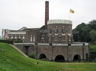
The Henry Ford Museum in Dearborn, Michigan houses a replica of a 1788 Watt rotative engine. It is a full-scale working model of a Boulton-Watt engine. The American industrialist Henry Ford commissioned the replica engine from the English manufacturer Charles Summerfield in 1932.[18] The museum also holds an original Boulton and Watt atmospheric pump engine, originally used for canal pumping in Birmingham,[19] illustrated below, and in use in situ at the Bowyer Street pumping station,[20][21] from 1796 until 1854, and afterwards removed to Dearborn in 1929.
An other one is preserved at Fumel factory, France.
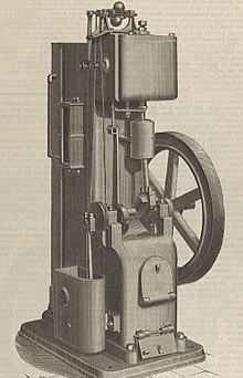
In the 1880s, Hathorn Davey and Co / Leeds produced a 1hp / 125 rpm atmospheric engine with external condenser but without steam expansion. It has been argued that this was probably the last commercial atmospheric engine to be manufactured. As an atmospheric engine, it did not have a pressurized boiler. It was intended for small businesses.[22]
Daveys Engine 1885
Recent developments
Watt's Expansion Engine is generally considered as of historic interest only. There are however some recent developments which may lead to a renaissance of the technology. Today, there is an enormous amount of waste steam and waste heat with temperatures between 100 and 150°C generated by industry. In addition, solarthermal collectors, geothermal energy sources and biomass reactors produce heat in this temperature range. There are technologies to utilise this energy, in particular the Organic Rankine Cycle. In principle, these are steam turbines which do not use water but a fluid (a refrigerant) which evaporates at temperatures below 100°C. Such systems are however fairly complex. They work with pressures of 6 to 20 bars, so that the whole system has to be completely sealed.
The Expansion Engine can offer significant advantages here, in particular for lower power ratings of 2 to 100kW: with expansion ratios of 1:5, the theoretical efficiency reaches 15%, which is in the range of ORC systems. The Expansion Engine uses water as working fluid which is simple, cheap, non-toxic, non-flammable and non-corrosive. It works at pressure near and below atmospheric, so that sealing is not a problem. And it is a simple machine, implying cost effectiveness. Researchers from the University of Southampton / UK are currently developing a modern version of Watt's engine in order to generate energy from waste steam and waste heat. They improved the theory, demonstrating that theoretical efficiencies of up to 17.4% (and actual efficiencies of 11%) are possible.[23]
The 25 Watt Experimental Condensing Engine built and tested at Southampton University
In order to demonstrate the principle, a 25 watt experimental model engine was built and tested. The engine incorporates steam expansion as well as new features such as electronic control. The picture shows the model built and tested in 2016.[24] Currently, a project to build and test a scaled-up 2kW engine is under preparation.[25]
Ivan Polzunov made a dual-piston steam engine in 1766, but died before he could mass-produce it
Related Research Articles
James Watt was a Scottish inventor, mechanical engineer, and chemist who improved on Thomas Newcomen's 1712 Newcomen steam engine with his Watt steam engine in 1776, which was fundamental to the changes brought by the Industrial Revolution in both his native country Great Britain, and the rest of the world.
A steam engine is a heat engine that performs mechanical work using steam as its working fluid. The steam engine uses the force produced by steam pressure to push a piston back and forth inside a cylinder. This pushing force can be transformed, by a connecting rod and crank, into rotational force for work. The term "steam engine" is most commonly applied to reciprocating engines as just described, although some authorities have also referred to the steam turbine and devices such as Hero's aeolipile as "steam engines". The essential feature of steam engines is that they are external combustion engines, where the working fluid is separated from the combustion products. The ideal thermodynamic cycle used to analyze this process is called the Rankine cycle. In general usage, the term steam engine can refer to either complete steam plants, such as railway steam locomotives and portable engines, or may refer to the piston or turbine machinery alone, as in the beam engine and stationary steam engine.
Thomas Newcomen was an English inventor who created the atmospheric engine, the first practical fuel-burning engine in 1712. He was an ironmonger by trade and a Baptist lay preacher by calling.
Thomas Savery was an English inventor and engineer. He invented the first commercially used steam-powered device, a steam pump which is often referred to as the "Savery engine". Savery's steam pump was a revolutionary method of pumping water, which improved mine drainage and made widespread public water supply practicable.
The atmospheric engine was invented by Thomas Newcomen in 1712, and is often referred to as the Newcomen fire engine or simply as a Newcomen engine. The engine was operated by condensing steam drawn into the cylinder, thereby creating a partial vacuum which allowed the atmospheric pressure to push the piston into the cylinder. It was historically significant as the first practical device to harness steam to produce mechanical work. Newcomen engines were used throughout Britain and Europe, principally to pump water out of mines. Hundreds were constructed throughout the 18th century.
Stationary steam engines are fixed steam engines used for pumping or driving mills and factories, and for power generation. They are distinct from locomotive engines used on railways, traction engines for heavy steam haulage on roads, steam cars, agricultural engines used for ploughing or threshing, marine engines, and the steam turbines used as the mechanism of power generation for most nuclear power plants.
Steam power developed slowly over a period of several hundred years, progressing through expensive and fairly limited devices in the early 17th century, to useful pumps for mining in 1700, and then to Watt's improved steam engine designs in the late 18th century. It is these later designs, introduced just when the need for practical power was growing due to the Industrial Revolution, that truly made steam power commonplace.
Improvements to the steam engine were some of the most important technologies of the Industrial Revolution, although steam did not replace water power in importance in Britain until after the Industrial Revolution. From Englishman Thomas Newcomen's atmospheric engine, of 1712, through major developments by Scottish inventor and mechanical engineer James Watt, the steam engine began to be used in many industrial settings, not just in mining, where the first engines had been used to pump water from deep workings. Early mills had run successfully with water power, but by using a steam engine a factory could be located anywhere, not just close to a water source. Water power varied with the seasons and was not always available.
A beam engine is a type of steam engine where a pivoted overhead beam is used to apply the force from a vertical piston to a vertical connecting rod. This configuration, with the engine directly driving a pump, was first used by Thomas Newcomen around 1705 to remove water from mines in Cornwall. The efficiency of the engines was improved by engineers including James Watt, who added a separate condenser; Jonathan Hornblower and Arthur Woolf, who compounded the cylinders; and William McNaught, who devised a method of compounding an existing engine. Beam engines were first used to pump water out of mines or into canals but could be used to pump water to supplement the flow for a waterwheel powering a mill.
This timeline of heat engine technology describes how heat engines have been known since antiquity but have been made into increasingly useful devices since the 17th century as a better understanding of the processes involved was gained. A heat engine is any system that converts heat to mechanical energy, which can then be used to do mechanical work.They continue to be developed today.
Jonathan Hornblower was an English pioneer of steam power.
A Cornish engine is a type of steam engine developed in Cornwall, England, mainly for pumping water from a mine. It is a form of beam engine that uses steam at a higher pressure than the earlier engines designed by James Watt. The engines were also used for powering man engines to assist the underground miners' journeys to and from their working levels, for winching materials into and out of the mine, and for powering on-site ore stamping machinery.
Engine efficiency of thermal engines is the relationship between the total energy contained in the fuel, and the amount of energy used to perform useful work. There are two classifications of thermal engines-
Internal combustion and
External combustion engines.
The first recorded rudimentary steam engine was the aeolipile mentioned by Vitruvius between 30 and 15 BC and, described by Heron of Alexandria in 1st-century Roman Egypt. Several steam-powered devices were later experimented with or proposed, such as Taqi al-Din's steam jack, a steam turbine in 16th-century Ottoman Egypt, Denis Papin's working model of the steam digester in 1679 and Thomas Savery's steam pump in 17th-century England. In 1712, Thomas Newcomen's atmospheric engine became the first commercially successful engine using the principle of the piston and cylinder, which was the fundamental type of steam engine used until the early 20th century. The steam engine was used to pump water out of coal mines.
The Whitbread Engine preserved in the Powerhouse Museum in Sydney, Australia, built in 1785, is one of the first rotative steam engines ever built, and is the oldest surviving. A rotative engine is a type of beam engine where the reciprocating motion of the beam is converted to rotary motion, producing a continuous power source suitable for driving machinery.
A vacuum engine refers to any kind of engine which derives its force from air pressure against one side of the piston, while also having a partial vacuum on the other side of it. This pressure differential can be the result of heat transfer, or mechanically produced by an external source.
Old Bess is an early beam engine built by the partnership of Boulton and Watt. The engine was constructed in 1777 and worked until 1848.
A cataract was a speed governing device used for early single-acting beam engines, particularly atmospheric engines and Cornish engines. It was a kind of water clock.
Resolution was an early beam engine, installed between 1781 and 1782 at Coalbrookdale as a water-returning engine to power the blast furnaces and ironworks there. It was one of the last water-returning engines to be constructed, before the rotative beam engine made this type of engine obsolete.
The Newcomen Memorial Engine is a preserved beam engine in Dartmouth, Devon. It was preserved as a memorial to Thomas Newcomen, inventor of the beam engine, who was born in Dartmouth.
1 2 Rosen, William (2012). The Most Powerful Idea in the World: A Story of Steam, Industry and Invention. University of Chicago Press. p.137. ISBN978-0226726342.
↑ Society of Gentlemen (1763). A new and complete dictionary of Art and sciences; comprehending all the branches of useful knowledge, with accurate descriptions as well of the various machines, tools, figures and schemes necessary for illustrating them, as of the classes, kinds, preparations, and uses of natural productions, whether animals, vegetables, minerals, fossils, or fluids; together with the kingdoms, provinces, cities, towns and other remarkable places throughout the world. Illustrated with above three hundred copper-plates engraved by Mr. Jefferys (The second edition, with many additions, and other improvements.ed.). London: W.Owen. p.1073 (table).
This page is based on this Wikipedia article Text is available under the CC BY-SA 4.0 license; additional terms may apply. Images, videos and audio are available under their respective licenses.


