
A loudspeaker is an electroacoustic transducer that converts an electrical audio signal into a corresponding sound. A speaker system, also often simply referred to as a speaker or loudspeaker, comprises one or more such speaker drivers, an enclosure, and electrical connections possibly including a crossover network. The speaker driver can be viewed as a linear motor attached to a diaphragm which couples that motor's movement to motion of air, that is, sound. An audio signal, typically from a microphone, recording, or radio broadcast, is amplified electronically to a power level capable of driving that motor in order to reproduce the sound corresponding to the original unamplified electronic signal. This is thus the opposite function to the microphone; indeed the dynamic speaker driver, by far the most common type, is a linear motor in the same basic configuration as the dynamic microphone which uses such a motor in reverse, as a generator.

Audio crossovers are a type of electronic filter circuitry that splits an audio signal into two or more frequency ranges, so that the signals can be sent to loudspeaker drivers that are designed to operate within different frequency ranges. The crossover filters can be either active or passive. They are often described as two-way or three-way, which indicate, respectively, that the crossover splits a given signal into two frequency ranges or three frequency ranges. Crossovers are used in loudspeaker cabinets, power amplifiers in consumer electronics and pro audio and musical instrument amplifier products. For the latter two markets, crossovers are used in bass amplifiers, keyboard amplifiers, bass and keyboard speaker enclosures and sound reinforcement system equipment.
A tweeter or treble speaker is a special type of loudspeaker that is designed to produce high audio frequencies, typically deliver high frequencies up to 100 kHz. The name is derived from the high pitched sounds made by some birds (tweets), especially in contrast to the low woofs made by many dogs, after which low-frequency drivers are named (woofers).
A mid-range speaker is a loudspeaker driver that reproduces sound in the frequency range from 250 to 2000 Hz.
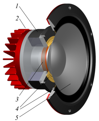
A woofer or bass speaker is a technical term for a loudspeaker driver designed to produce low frequency sounds, typically from 20 Hz up to a few hundred Hz. A subwoofer can take the lower part of this range, normally up to 80 Hz. The name is from the onomatopoeic English word for a dog's deep bark, "woof". The most common design for a woofer is the electrodynamic driver, which typically uses a stiff paper cone, driven by a voice coil surrounded by a magnetic field.

Headphones are a pair of small loudspeaker drivers worn on or around the head over a user's ears. They are electroacoustic transducers, which convert an electrical signal to a corresponding sound. Headphones let a single user listen to an audio source privately, in contrast to a loudspeaker, which emits sound into the open air for anyone nearby to hear. Headphones are also known as earphones or, colloquially, cans. Circumaural and supra-aural headphones use a band over the top of the head to hold the speakers in place. Another type, known as earbuds or earpieces, consists of individual units that plug into the user's ear canal. A third type are bone conduction headphones, which typically wrap around the back of the head and rest in front of the ear canal, leaving the ear canal open. In the context of telecommunication, a headset is a combination of a headphone and microphone.
An electrostatic loudspeaker (ESL) is a loudspeaker design in which sound is generated by the force exerted on a membrane suspended in an electrostatic field.

A horn loudspeaker is a loudspeaker or loudspeaker element which uses an acoustic horn to increase the overall efficiency of the driving element(s). A common form (right) consists of a compression driver which produces sound waves with a small metal diaphragm vibrated by an electromagnet, attached to a horn, a flaring duct to conduct the sound waves to the open air. Another type is a woofer driver mounted in a loudspeaker enclosure which is divided by internal partitions to form a zigzag flaring duct which functions as a horn; this type is called a folded horn speaker. The horn serves to improve the coupling efficiency between the speaker driver and the air. The horn can be thought of as an "acoustic transformer" that provides impedance matching between the relatively dense diaphragm material and the less-dense air. The result is greater acoustic output power from a given driver.
Thiele/Small parameters are a set of electromechanical parameters that define the specified low frequency performance of a loudspeaker driver. These parameters are published in specification sheets by driver manufacturers so that designers have a guide in selecting off-the-shelf drivers for loudspeaker designs. Using these parameters, a loudspeaker designer may simulate the position, velocity and acceleration of the diaphragm, the input impedance and the sound output of a system comprising a loudspeaker and enclosure. Many of the parameters are strictly defined only at the resonant frequency, but the approach is generally applicable in the frequency range where the diaphragm motion is largely pistonic, i.e., when the entire cone moves in and out as a unit without cone breakup.
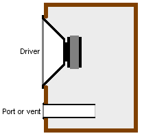
A bass reflex system is a type of loudspeaker enclosure that uses a port (hole) or vent cut into the cabinet and a section of tubing or pipe affixed to the port. This port enables the sound from the rear side of the diaphragm to increase the efficiency of the system at low frequencies as compared to a typical sealed- or closed-box loudspeaker or an infinite baffle mounting.
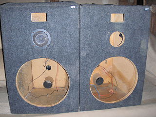
A loudspeaker enclosure or loudspeaker cabinet is an enclosure in which speaker drivers and associated electronic hardware, such as crossover circuits and, in some cases, power amplifiers, are mounted. Enclosures may range in design from simple, homemade DIY rectangular particleboard boxes to very complex, expensive computer-designed hi-fi cabinets that incorporate composite materials, internal baffles, horns, bass reflex ports and acoustic insulation. Loudspeaker enclosures range in size from small "bookshelf" speaker cabinets with 4-inch (10 cm) woofers and small tweeters designed for listening to music with a hi-fi system in a private home to huge, heavy subwoofer enclosures with multiple 18-inch (46 cm) or even 21-inch (53 cm) speakers in huge enclosures which are designed for use in stadium concert sound reinforcement systems for rock music concerts.

An acoustic transmission line is the use of a long duct, which acts as an acoustic waveguide and is used to produce or transmit sound in an undistorted manner. Technically it is the acoustic analog of the electrical transmission line, typically conceived as a rigid-walled duct or tube, that is long and thin relative to the wavelength of sound present in it.

An electrodynamic speaker driver, often called simply a speaker driver when the type is implicit, is an individual transducer that converts an electrical audio signal to sound waves. While the term is sometimes used interchangeably with the term speaker (loudspeaker), it is usually applied to specialized transducers which reproduce only a portion of the audible frequency range. For high fidelity reproduction of sound, multiple loudspeakers are often mounted in the same enclosure, each reproducing a different part of the audible frequency range. In this case the individual speakers are referred to as drivers and the entire unit is called a loudspeaker. Drivers made for reproducing high audio frequencies are called tweeters, those for middle frequencies are called mid-range drivers, and those for low frequencies are called woofers, while those for very low bass range are subwoofers. Less common types of drivers are supertweeters and rotary woofers.
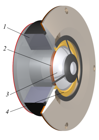
A coaxial loudspeaker is a loudspeaker system in which the individual driver units radiate sound from the same point or axis. Two general types exist: one is a compact design using two or three speaker drivers, usually in car audio, and the other is a two-way high-power design for professional audio, also known as single-source or dual-concentric loudspeakers. The design is favored for its compactness and behavior as an audio point source.

DUPLEX was the trade name given by Altec Lansing to its line of coaxial loudspeakers, beginning with the first model 601 in 1943. However, the name was most commonly associated with the subsequent model 604 which was a seminal loudspeaker that became a milestone in loudspeaker development. Well over a dozen different models carried the Duplex name over a near 50-year period. The vast majority consisted of a high frequency (HF) compression driver mounted to the back of a large diameter paper cone low frequency (LF) driver. However, there were also a few models with small diameter LF cones and direct radiator tweeters.

David W. Gunness is an American audio engineer, electrical engineer and inventor. He is known for his work on loudspeaker design, especially high-output professional horn loudspeakers for public address, studio, theater, nightclub, concert and touring uses.
Cliff Henricksen is a musician, inventor and audio technologist. He is self-taught as a musician with a graduate degree in mechanical engineering at Massachusetts Institute of Technology (MIT). Throughout his career Cliff has found innovative ways to apply engineering basics to electro acoustics and to audio technology as it applies to music and in particular to live music performance. He has invented and engineered a wide variety of technologies and products well known in the world of professional audio. Today he balances work in audio and work as a performing musician.

In a loudspeaker, a phase plug, phasing plug or acoustical transformer is a mechanical interface between a speaker driver and the audience. The phase plug extends high frequency response because it guides waves outward toward the listener rather than allowing them to interact destructively near the driver.
A transmission line loudspeaker is a loudspeaker enclosure design which uses the topology of an acoustic transmission line within the cabinet, compared to the simpler enclosures used by sealed (closed) or ported designs. Instead of reverberating in a fairly simple damped enclosure, sound from the back of the bass speaker is directed into a long damped pathway within the speaker enclosure, which allows far greater control and use of speaker energy and the resulting sound.
In a loudspeaker, power compression or thermal compression is a loss of efficiency observed as the voice coil heats up under operation, increasing the DC resistance of the voice coil and decreasing the effective available power of the audio amplifier. A loudspeaker that becomes hot from use may not produce as much sound pressure level as when it is cold. The problem is much greater for hard-driven professional concert systems than it is for loudspeakers in the home, where it is rarely seen. Two main pathways exist to mitigate the problem: to design a way for the voice coil to dissipate more heat during operation, and to design a more efficient transducer that generates less heat for a given sound output level.

