Current clamp

Last updated
Clamp meter Clampmeter Fluke 337.jpg
Clamp meter

In electrical and electronic engineering, a current clamp, also known as current probe, is an electrical device with jaws which open to allow clamping around an electrical conductor. This allows measurement of the current in a conductor without the need to make physical contact with it, or to disconnect it for insertion through the probe.

Contents

Current clamps are typically used to read the magnitude of alternating current (AC) and, with additional instrumentation, the phase and waveform can also be measured. Some clamp meters can measure currents of 1000 A and more. Hall effect and vane type clamps can also measure direct current (DC).

Types of current clamp

Current transformer

A common form of current clamp comprises a split ring made of ferrite or soft iron. A wire coil is wound round one or both halves, forming one winding of a current transformer. The conductor it is clamped around forms the other winding. Like any transformer this type works only with AC or pulse waveforms, with some examples extending into the megahertz range.

When measuring current, the subject conductor forms the primary winding and the coil forms the secondary.

This type may also be used in reverse, to inject current into the conductor, for example in electromagnetic compatibility susceptibility testing to induce an interference current. Usually, the injection probe is specifically designed for this purpose. In this mode, the coil forms the primary and the test conductor the secondary.

Iron vane

In the iron vane type, the magnetic flux in the core directly affects a moving iron vane, allowing both AC and DC to be measured, and gives a true root mean square (RMS) value for non-sinusoidal AC waveforms. Due to its physical size it is generally limited to power transmission frequencies up to around 100 Hz.

The vane is usually fixed directly to the display mechanism of an analogue (moving pointer) clamp meter. The calibration of the instrument is clearly non-linear.

Hall effect

The Hall effect type is more sensitive and is able to measure both DC and AC, [1] in some examples up to the kilohertz (thousands of hertz) range. This type was often used with oscilloscopes, and with high-end computerized digital multimeters, however, they are becoming common place for more general use.

Rogowski coil

Resembling a current clamp in appearance and function is the Rogowski coil current sensor. This coreless transformer is used in clamp meters and power monitoring loggers. It has the advantage of better linearity, having no core to saturate, it can be made flexible, and does not require any magnetic or electrical contact at the opening end. [2] The Rogowski coil gives a voltage proportional to the rate of change of current in the primary cable, so more signal processing is needed before the sensed values can be displayed.
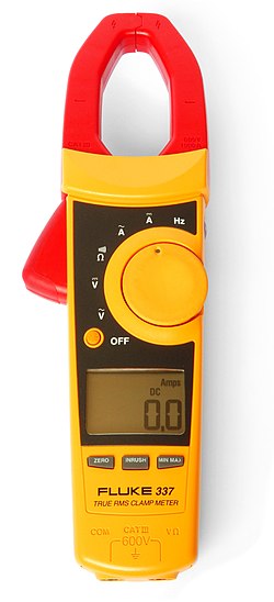
Clamp meter

A digital clamp meter Clampmeter.jpg
A digital clamp meter
A multimeter with built-in clamp. Pushing the large button at the bottom opens the lower jaw of the clamp, allowing the clamp to be placed around a conductor. Tongtester.jpg
A multimeter with built-in clamp. Pushing the large button at the bottom opens the lower jaw of the clamp, allowing the clamp to be placed around a conductor.

An electrical meter with integral AC current clamp is known as a clamp meter, clamp-on ammeter, tong tester, or colloquially as an amp clamp.

A clamp meter measures the vector sum of the currents flowing in all the conductors passing through the probe, which depends on the phase relationship of the currents. Only one conductor is normally passed through the probe. In particular if the clamp is closed around a two-conductor cable carrying power to equipment, the same current flows down one conductor and up the other; the meter correctly reads a net current of zero. As electrical cables for equipment have both insulated conductors (and possibly an earth wire) bonded together, clamp meters are often used with what is essentially a short extension cord with the two conductors separated, so that the clamp can be placed around only one conductor of this extension.

A relatively recent development is a multi-conductor clamp meter with several sensor coils around the jaws of the clamp. This could be clamped around standard two- or three-conductor single-phase cables to provide a readout of the current flowing through the load, [3] with no need to separate the conductors. However, the particular sensing mechanism is more prone to erroneous measurement and careful operation is required. [4]

The reading produced by a conductor carrying a very low current can be increased by winding the conductor around the clamp several times; the meter reading divided by the number of turns is the current, [5] with some loss of accuracy due to inductive effects.

Clamp meters are used by electricians, sometimes with the clamp incorporated into a general purpose multimeter.

It is simple to measure very high currents (hundreds of amperes) with the appropriate current transformer. Accurate measurement of low currents (a few milliamperes) with a current transformer clamp is more difficult. The range of any given meter can be extended by passing the conductor through the jaw multiple times. For example a 0–200 A meter can be turned into a 0–20 A meter by winding the conductor 10 times around the jaw's core.

Columbia iron vane type clamp-on ammeter, with heads for different ranges Ammeter-Columbia-iron-vane-type-clamp-on-ammeter.jpg
Columbia iron vane type clamp-on ammeter, with heads for different ranges

Less-expensive clamp meters use a rectifier circuit which actually reads mean current, but is calibrated to display the RMS current corresponding to the measured mean, giving a correct RMS reading only if the current is a sine wave. For other waveforms readings will be incorrect; when these simpler meters are used with non-sinusoidal loads such as the ballasts used with fluorescent lamps or high-intensity discharge lamps or most modern computer and electronic equipment, readings can be quite inaccurate. Meters which respond to true RMS rather than mean current are described as "true RMS".

Typical hand-held Hall effect units can read currents as low as 200 mA, and units that can read down to 1 mA are available.

The Columbia tong test ammeter (illustrated) is an example of the iron vane type, used for measuring large AC currents up to 1000 amperes. The iron jaws of the meter direct the magnetic field surrounding the conductor to an iron vane that is attached to the needle of the meter. The iron vane moves in proportion to the strength of the magnetic field, and thus produces a meter indication proportional to the current. This type of ammeter can measure both AC and DC currents and provides a true RMS current measurement of non-sinusoidal or distorted AC waveforms. Interchangeable meter movements can be installed in the clamping assembly to provide various full-scale current values up to 1000 amperes. The iron vane is in a small cylinder that is inserted in a space at the hinged end of the clamp-on jaws. Several jaw sizes are available for clamping around large conductors and bus bars up to 4+12 inches (110 mm) wide. [5] As the illustration shows, the scale is very non-linear and unsuitable for measuring low currents, with currents of less than half the full-scale deflection crammed into a short section of the dial.

Power meter, energy analyzer

Clamp probes are used with some meters to measure electrical power and energy. The clamp measures the current and other circuitry the voltage; the true power is the product of the instantaneous voltage and current integrated over a cycle. Comprehensive meters designed to measure many parameters of electrical energy (power factor, distortion, instantaneous power as a function of time, phase relationships, etc.), use this principle. A single clamp is used for single-phase measurements; with an appropriate instrument with three clamps, measurements may be made on three-phase power systems.

Related Research Articles

<span class="mw-page-title-main">Ammeter</span> Device that measures electric current

An ammeter is an instrument used to measure the current in a circuit. Electric currents are measured in amperes (A), hence the name. For direct measurement, the ammeter is connected in series with the circuit in which the current is to be measured. An ammeter usually has low resistance so that it does not cause a significant voltage drop in the circuit being measured.

<span class="mw-page-title-main">Electromagnetic coil</span> Electrical component

An electromagnetic coil is an electrical conductor such as a wire in the shape of a coil. Electromagnetic coils are used in electrical engineering, in applications where electric currents interact with magnetic fields, in devices such as electric motors, generators, inductors, electromagnets, transformers, sensor coils such as in medical FMRi imaging devices with coils going upto 3-7 and even higher Tesla. Either an electric current is passed through the wire of the coil to generate a magnetic field, or conversely, an external time-varying magnetic field through the interior of the coil generates an EMF (voltage) in the conductor.

<span class="mw-page-title-main">Transformer</span> Device to couple energy between circuits

In electrical engineering, a transformer is a passive component that transfers electrical energy from one electrical circuit to another circuit, or multiple circuits. A varying current in any coil of the transformer produces a varying magnetic flux in the transformer's core, which induces a varying electromotive force (EMF) across any other coils wound around the same core. Electrical energy can be transferred between separate coils without a metallic (conductive) connection between the two circuits. Faraday's law of induction, discovered in 1831, describes the induced voltage effect in any coil due to a changing magnetic flux encircled by the coil.

<span class="mw-page-title-main">Voltmeter</span> Instrument used for measuring voltage

A voltmeter is an instrument used for measuring electric potential difference between two points in an electric circuit. It is connected in parallel. It usually has a high resistance so that it takes negligible current from the circuit.

The amplitude of a periodic variable is a measure of its change in a single period. The amplitude of a non-periodic signal is its magnitude compared with a reference value. There are various definitions of amplitude, which are all functions of the magnitude of the differences between the variable's extreme values. In older texts, the phase of a periodic function is sometimes called the amplitude.

<span class="mw-page-title-main">Multimeter</span> Electronic measuring instrument that combines several measurement functions in one unit

A multimeter is a measuring instrument that can measure multiple electrical properties. A typical multimeter can measure voltage, resistance, and current, in which case can be used as a voltmeter, ohmmeter, and ammeter. Some feature the measurement of additional properties such as temperature and capacitance.

<span class="mw-page-title-main">Inductive coupling</span>

In electrical engineering, two conductors are said to be inductively coupled or magnetically coupled when they are configured in a way such that change in current through one wire induces a voltage across the ends of the other wire through electromagnetic induction. A changing current through the first wire creates a changing magnetic field around it by Ampere's circuital law. The changing magnetic field induces an electromotive force (EMF) voltage in the second wire by Faraday's law of induction. The amount of inductive coupling between two conductors is measured by their mutual inductance.

In electrical engineering, the power factor of an AC power system is defined as the ratio of the real power absorbed by the load to the apparent power flowing in the circuit. Real power is the average of the instantaneous product of voltage and current and represents the capacity of the electricity for performing work. Apparent power is the product of root mean square (RMS) current and voltage. Due to energy stored in the load and returned to the source, or due to a non-linear load that distorts the wave shape of the current drawn from the source, the apparent power may be greater than the real power, so more current flows in the circuit than would be required to transfer real power alone. A power factor magnitude of less than one indicates the voltage and current are not in phase, reducing the average product of the two. A negative power factor occurs when the device generates real power, which then flows back towards the source.

<span class="mw-page-title-main">Alternating current</span> Electric current that periodically reverses direction

Alternating current (AC) is an electric current that periodically reverses direction and changes its magnitude continuously with time, in contrast to direct current (DC), which flows only in one direction. Alternating current is the form in which electric power is delivered to businesses and residences, and it is the form of electrical energy that consumers typically use when they plug kitchen appliances, televisions, fans and electric lamps into a wall socket. The abbreviations AC and DC are often used to mean simply alternating and direct, respectively, as when they modify current or voltage.

<span class="mw-page-title-main">Rogowski coil</span> Device for measuring alternating current

A Rogowski coil, named after Walter Rogowski, is an electrical device for measuring alternating current (AC) or high-speed current pulses. It sometimes consists of a helical coil of wire with the lead from one end returning through the centre of the coil to the other end so that both terminals are at the same end of the coil. This approach is sometimes referred to as a counter-wound Rogowski.

<span class="mw-page-title-main">Current transformer</span> Transformer used to scale alternating current, used as sensor for AC power

A current transformer (CT) is a type of transformer that is used to reduce or multiply an alternating current (AC). It produces a current in its secondary which is proportional to the current in its primary.

<span class="mw-page-title-main">AC power</span> Power in alternating current systems

In an electric circuit, instantaneous power is the time rate of flow of energy past a given point of the circuit. In alternating current circuits, energy storage elements such as inductors and capacitors may result in periodic reversals of the direction of energy flow. Its SI unit is the watt.

<span class="mw-page-title-main">Wattmeter</span> Device that measures electric power

The wattmeter is an instrument for measuring the electric active power in watts of any given circuit. Electromagnetic wattmeters are used for measurement of utility frequency and audio frequency power; other types are required for radio frequency measurements.

<span class="mw-page-title-main">Choke (electronics)</span> Inductor used as a low-pass filter

In electronics, a choke is an inductor used to block higher-frequency alternating currents (AC) while passing direct current (DC) and lower-frequency ACs in a circuit. A choke usually consists of a coil of insulated wire often wound on a magnetic core, although some consist of a doughnut-shaped ferrite bead strung on a wire. The choke's impedance increases with frequency. Its low electrical resistance passes both AC and DC with little power loss, but its reactance limits the amount of AC passed.

<span class="mw-page-title-main">Flyback converter</span> Type of voltage converter circuit

The flyback converter is used in both AC/DC, and DC/DC conversion with galvanic isolation between the input and any outputs. The flyback converter is a buck-boost converter with the inductor split to form a transformer, so that the voltage ratios are multiplied with an additional advantage of isolation.

<span class="mw-page-title-main">Transformer types</span> Overview of electrical transformer types

A variety of types of electrical transformer are made for different purposes. Despite their design differences, the various types employ the same basic principle as discovered in 1831 by Michael Faraday, and share several key functional parts.

In an electric power system, a harmonic of a voltage or current waveform is a sinusoidal wave whose frequency is an integer multiple of the fundamental frequency. Harmonic frequencies are produced by the action of non-linear loads such as rectifiers, discharge lighting, or saturated electric machines. They are a frequent cause of power quality problems and can result in increased equipment and conductor heating, misfiring in variable speed drives, and torque pulsations in motors and generators.

Instrument transformers are high accuracy class electrical devices used to isolate or transform voltage or current levels. The most common usage of instrument transformers is to operate instruments or metering from high voltage or high current circuits, safely isolating secondary control circuitry from the high voltages or currents. The primary winding of the transformer is connected to the high voltage or high current circuit, and the meter or relay is connected to the secondary circuit.

<span class="mw-page-title-main">Current sensing</span>

In electrical engineering, current sensing is any one of several techniques used to measure electric current. The measurement of current ranges from picoamps to tens of thousands of amperes. The selection of a current sensing method depends on requirements such as magnitude, accuracy, bandwidth, robustness, cost, isolation or size. The current value may be directly displayed by an instrument, or converted to digital form for use by a monitoring or control system.

This glossary of electrical and electronics engineering is a list of definitions of terms and concepts related specifically to electrical engineering and electronics engineering. For terms related to engineering in general, see Glossary of engineering.

References

  1. Portal, EEP-Electrical Engineering (May 6, 2012). "An Overview Of Clamp Meter".
  2. "Inside Flexible Coil Clamp Meters". www.fluke.com.
  3. Megger MMC850 clamp meter specification. [ permanent dead link ] Designed to read current even if both conductors enclosed.
  4. "Anyone know of a multicore clamp meter?". Electricians Forums | Electrical Safety Advice | Talk Electrician Forum. Retrieved 2023-01-12.
  5. 1 2 "Weschler Instruments: Columbia Tong Ammeters" (PDF).