Type of field where the net flow of electromagnetic energy is zero
"Evanesce" redirects here. For the album by Anatomy of a Ghost, see Evanesce (album).
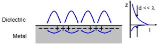
Schematic representation of a surface wave (surface plasmon polariton) propagating along a metal-dielectric interface. The fields away from the surface die off exponentially (right hand graph) and those fields are thus described as evanescent in the z direction
In electromagnetics, an evanescent field, or evanescent wave, is an oscillating electric and/or magnetic field that does not propagate as an electromagnetic wave but whose energy is spatially concentrated in the vicinity of the source (oscillating charges and currents). Even when there is a propagating electromagnetic wave produced (e.g., by a transmitting antenna), one can still identify as an evanescent field the component of the electric or magnetic field that cannot be attributed to the propagating wave observed at a distance of many wavelengths (such as the far field of a transmitting antenna).
A hallmark of an evanescent field is that there is no net energy flow in that region. Since the net flow of electromagnetic energy is given by the average Poynting vector, this means that the Poynting vector in these regions, as averaged over a complete oscillation cycle, is zero.[lower-alpha 1]
Use of the term
In many cases one cannot simply say that a field is or is not "evanescent" – having the Poynting vector average to zero in some direction (or all directions). In most cases where they exist, evanescent fields are simply thought of and referred to the same as all other electric or magnetic fields involved, without any special recognition of those fields' evanescence. The term's use is mostly limited to distinguishing a part of a field or solution in those cases where one might only expect the fields of a propagating wave.
For instance, in the illustration at the top of the article, energy is indeed carried in the horizontal direction. However, in the vertical direction, the field strength drops off exponentially with increasing distance above the surface. This leaves most of the field concentrated in a thin boundary layer very close to the interface; for that reason, it is referred to as a surface wave.[1] However, despite energy flowing horizontally, along the vertical there is no net propagation of energy away from (or toward) the surface, so that one could properly describe the field as being "evanescent in the vertical direction". This is one example of the context dependence of the term.
Everyday electronic devices and electrical appliances are surrounded by large fields which are evanescent; their operation involves alternating voltages (producing an electric field between them) and alternating currents (producing a magnetic field around them) which are expected to only carry power along internal wires, but not to the outsides of the devices. Even though the term "evanescent" is not mentioned in this ordinary context, the appliances' designers still may be concerned with maintaining evanescence, in order to prevent or limit production of a propagating electromagnetic wave, which would lead to radiation loss, since a propagating wave "steals" its power from the circuitry or donates unwanted interference.
The term "evanescent field" does arise in various contexts where a propagating electromagnetic wave is involved (even if confined). The term then differentiates electromagnetic field components that accompany the propagating wave, but which do not themselves propagate. In other, similar cases, where a propagating electromagnetic wave would normally be expected (such as light refracted at the interface between glass and air), the term is invoked to describe that part of the field where the wave is suppressed (such as light traveling through glass, impinging on a glass-to-air interface but beyond the critical angle).
Although all electromagnetic fields are classically governed according to Maxwell's equations, different technologies or problems have certain types of expected solutions, and when the primary solutions involve wave propagation the term evanescent is frequently applied to field components or solutions which do not share that property.
For instance, the propagation constant of a hollow metal waveguide is a strong function of frequency (a dispersion relation). Below a certain frequency (the cut-off frequency) the propagation constant becomes an imaginary number. A solution to the wave equation having an imaginary wavenumber does not propagate as a wave but falls off exponentially, so the field excited at that lower frequency is considered evanescent. It can also be simply said that propagation is "disallowed" for that frequency.
The formal solution to the wave equation can describe modes having an identical form, but the change of the propagation constant from real to imaginary as the frequency drops below the cut-off frequency totally changes the physical nature of the result. The solution may be described as a "cut-off mode" or an "evanescent mode";[2][3]:360 while a different author will just state that no such mode exists. Since the evanescent field corresponding to the mode was computed as a solution to the wave equation, it is often discussed as being an "evanescent wave" even though its properties (such as carrying no energy) are inconsistent with the definition of wave.
Although this article concentrates on electromagnetics, the term evanescent is used similarly in fields such as acoustics and quantum mechanics, where the wave equation arises from the physics involved. In these cases, solutions to the wave equation resulting in imaginary propagation constants are likewise called "evanescent", and have the essential property that no net energy is transferred, even though there is a non-zero field.
Evanescent wave applications
In optics and acoustics, evanescent waves are formed when waves traveling in a medium undergo total internal reflection at its boundary because they strike it at an angle greater than the critical angle.[4][5] The physical explanation for the existence of the evanescent wave is that the electric and magnetic fields (or pressure gradients, in the case of acoustical waves) cannot be discontinuous at a boundary, as would be the case if there was no evanescent wave field. In quantum mechanics, the physical explanation is exactly analogous—the Schrödinger wave-function representing particle motion normal to the boundary cannot be discontinuous at the boundary.
In electrical engineering, evanescent waves are found in the near-field region within one third of a wavelength of any radio antenna. During normal operation, an antenna emits electromagnetic fields into the surrounding nearfield region, and a portion of the field energy is reabsorbed, while the remainder is radiated as EM waves.
Recently, a graphene-based Bragg grating (one-dimensional photonic crystal) has been fabricated and demonstrated its competence for excitation of surface electromagnetic waves in the periodic structure using a prism coupling technique.[6]
In microscopy, systems that capture the information contained in evanescent waves can be used to create super-resolution images. Matter radiates both propagating and evanescent electromagnetic waves. Conventional optical systems capture only the information in the propagating waves and hence are subject to the diffraction limit. Systems that capture the information contained in evanescent waves, such as the superlens and near field scanning optical microscopy, can overcome the diffraction limit; however these systems are then limited by the system's ability to accurately capture the evanescent waves.[7] The limitation on their resolution is given by
where is the maximal wave vector that can be resolved, is the distance between the object and the sensor, and is a measure of the quality of the sensor.
More generally, practical applications of evanescent waves can be classified as (1) those in which the energy associated with the wave is used to excite some other phenomenon within the region of space where the original traveling wave becomes evanescent (for example, as in the total internal reflection fluorescence microscope) or (2) those in which the evanescent wave couples two media in which traveling waves are allowed, and hence permits the transfer of energy or a particle between the media (depending on the wave equation in use), even though no traveling-wave solutions are allowed in the region of space between the two media. An example of this is wave-mechanical tunnelling, and is known generally as evanescent wave coupling.
For example, consider total internal reflection in two dimensions, with the interface between the media lying on the x axis, the normal along y, and the polarization along z. One might expect that for angles leading to total internal reflection, the solution would consist of an incident wave and a reflected wave, with no transmitted wave at all, but there is no such solution that obeys Maxwell's equations. Maxwell's equations in a dielectric medium impose a boundary condition of continuity for the components of the fields E||, H||, Dy, and By. For the polarization considered in this example, the conditions on E|| and By are satisfied if the reflected wave has the same amplitude as the incident one, because these components of the incident and reflected waves superimpose destructively. Their Hx components, however, superimpose constructively, so there can be no solution without a non-vanishing transmitted wave. The transmitted wave cannot, however, be a sinusoidal wave, since it would then transport energy away from the boundary, but since the incident and reflected waves have equal energy, this would violate conservation of energy. We therefore conclude that the transmitted wave must be a non-vanishing solution to Maxwell's equations that is not a traveling wave, and the only such solutions in a dielectric are those that decay exponentially: evanescent waves.
Mathematically, evanescent waves can be characterized by a wave vector where one or more of the vector's components has an imaginary value. Because the vector has imaginary components, it may have a magnitude that is less than its real components.
For the plane of incidence as the plane at and the interface of the two mediums as the plane at , the wave vector of the transmitted wave has the form[8]
with and , where is the magnitude of the wave vector of the transmitted wave (so the wavenumber), is the angle of refraction, and and are the unit vectors along the axis direction and the axis direction respectively.
By using the Snell's law where , , and are the refractive index of the medium where the incident wave and the reflected wave exist, the refractive index of the medium where the transmitted wave exists, and the angle of incidence respectively,
If the polarization is perpendicular to the plane of incidence (along the direction), then the electric field of any of the waves (incident, reflected, or transmitted) can be expressed as
By assuming plane waves as , and substituting the transmitted wave vector into , we find for the transmitted wave:
where is the attenuation constant, and is the phase constant. is ignored since it does not physically make sense (the wave amplification along y the direction in this case).
Evanescent-wave coupling
Plot of 1/e-penetration depth of the evanescent wave against angle of incidence in units of wavelength for different refraction indices.
Especially in optics, evanescent-wave coupling refers to the coupling between two waves due to physical overlap of what would otherwise be described as the evanescent fields corresponding to the propagating waves.[9]
One classical example is frustrated total internal reflection (FTIR) in which the evanescent field very close (see graph) to the surface of a dense medium at which a wave normally undergoes total internal reflection overlaps another dense medium in the vicinity. This disrupts the totality of the reflection, diverting some power into the second medium.
Coupling between two optical waveguides may be effected by placing the fiber cores close together so that the evanescent field generated by one element excites a wave in the other fiber. This is used to produce fiber-optic splitters and in fiber tapping. At radio (and even optical) frequencies, such a device is called a directional coupler. The device is usually called a power divider in the case of microwave transmission and modulation.
Evanescent-wave coupling is synonymous with near field interaction in electromagnetic field theory. Depending on the nature of the source element, the evanescent field involved is either predominantly electric (capacitive) or magnetic (inductive), unlike (propagating) waves in the far field where these components are connected (identical phase, in the ratio of the impedance of free space). The evanescent wave coupling takes place in the non-radiative field near each medium and as such is always associated with matter; i.e., with the induced currents and charges within a partially reflecting surface. In quantum mechanics the wave function interaction may be discussed in terms of particles and described as quantum tunneling.
Applications
Evanescent wave coupling is commonly used in photonic and nanophotonic devices as waveguide sensors or couplers (see e.g., prism coupler).[10]
Evanescent wave coupling is used to excite, for example, dielectric microsphere resonators.
↑ Or, expressing the fields E and H as phasors, the complex Poynting vector has a zero real part.
Related Research Articles
Diffraction is the interference or bending of waves around the corners of an obstacle or through an aperture into the region of geometrical shadow of the obstacle/aperture. The diffracting object or aperture effectively becomes a secondary source of the propagating wave. Italian scientist Francesco Maria Grimaldi coined the word diffraction and was the first to record accurate observations of the phenomenon in 1660.
The Fresnel equations describe the reflection and transmission of light when incident on an interface between different optical media. They were deduced by French engineer and physicist Augustin-Jean Fresnel who was the first to understand that light is a transverse wave, when no one realized that the waves were electric and magnetic fields. For the first time, polarization could be understood quantitatively, as Fresnel's equations correctly predicted the differing behaviour of waves of the s and p polarizations incident upon a material interface.
In physics, total internal reflection (TIR) is the phenomenon in which waves arriving at the interface (boundary) from one medium to another are not refracted into the second ("external") medium, but completely reflected back into the first ("internal") medium. It occurs when the second medium has a higher wave speed than the first, and the waves are incident at a sufficiently oblique angle on the interface. For example, the water-to-air surface in a typical fish tank, when viewed obliquely from below, reflects the underwater scene like a mirror with no loss of brightness (Fig. 1).
Optical rotation, also known as polarization rotation or circular birefringence, is the rotation of the orientation of the plane of polarization about the optical axis of linearly polarized light as it travels through certain materials. Circular birefringence and circular dichroism are the manifestations of optical activity. Optical activity occurs only in chiral materials, those lacking microscopic mirror symmetry. Unlike other sources of birefringence which alter a beam's state of polarization, optical activity can be observed in fluids. This can include gases or solutions of chiral molecules such as sugars, molecules with helical secondary structure such as some proteins, and also chiral liquid crystals. It can also be observed in chiral solids such as certain crystals with a rotation between adjacent crystal planes or metamaterials.
In electrodynamics, elliptical polarization is the polarization of electromagnetic radiation such that the tip of the electric field vector describes an ellipse in any fixed plane intersecting, and normal to, the direction of propagation. An elliptically polarized wave may be resolved into two linearly polarized waves in phase quadrature, with their polarization planes at right angles to each other. Since the electric field can rotate clockwise or counterclockwise as it propagates, elliptically polarized waves exhibit chirality.
In electrodynamics, linear polarization or plane polarization of electromagnetic radiation is a confinement of the electric field vector or magnetic field vector to a given plane along the direction of propagation. The term linear polarization was coined by Augustin-Jean Fresnel in 1822. See polarization and plane of polarization for more information.
The Navier–Stokes equations are partial differential equations which describe the motion of viscous fluid substances. They were named after French engineer and physicist Claude-Louis Navier and the Irish physicist and mathematician George Gabriel Stokes. They were developed over several decades of progressively building the theories, from 1822 (Navier) to 1842–1850 (Stokes).
In mathematics, the Laplace operator or Laplacian is a differential operator given by the divergence of the gradient of a scalar function on Euclidean space. It is usually denoted by the symbols , (where is the nabla operator), or . In a Cartesian coordinate system, the Laplacian is given by the sum of second partial derivatives of the function with respect to each independent variable. In other coordinate systems, such as cylindrical and spherical coordinates, the Laplacian also has a useful form. Informally, the Laplacian Δf (p) of a function f at a point p measures by how much the average value of f over small spheres or balls centered at p deviates from f (p).
Fourier optics is the study of classical optics using Fourier transforms (FTs), in which the waveform being considered is regarded as made up of a combination, or superposition, of plane waves. It has some parallels to the Huygens–Fresnel principle, in which the wavefront is regarded as being made up of a combination of spherical wavefronts whose sum is the wavefront being studied. A key difference is that Fourier optics considers the plane waves to be natural modes of the propagation medium, as opposed to Huygens–Fresnel, where the spherical waves originate in the physical medium.
In linear algebra, linear transformations can be represented by matrices. If is a linear transformation mapping to and is a column vector with entries, then for some matrix , called the transformation matrix of . Note that has rows and columns, whereas the transformation is from to . There are alternative expressions of transformation matrices involving row vectors that are preferred by some authors.
Geometrical optics, or ray optics, is a model of optics that describes light propagation in terms of rays. The ray in geometrical optics is an abstraction useful for approximating the paths along which light propagates under certain circumstances.
In physics, the Hamilton–Jacobi equation, named after William Rowan Hamilton and Carl Gustav Jacob Jacobi, is an alternative formulation of classical mechanics, equivalent to other formulations such as Newton's laws of motion, Lagrangian mechanics and Hamiltonian mechanics.
In mathematics, the Helmholtz equation is the eigenvalue problem for the Laplace operator. It corresponds to the elliptic partial differential equation: where ∇2 is the Laplace operator, k2 is the eigenvalue, and f is the (eigen)function. When the equation is applied to waves, k is known as the wave number. The Helmholtz equation has a variety of applications in physics and other sciences, including the wave equation, the diffusion equation, and the Schrödinger equation for a free particle.
The Franz–Keldysh effect is a change in optical absorption by a semiconductor when an electric field is applied. The effect is named after the German physicist Walter Franz and Russian physicist Leonid Keldysh.
Sinusoidal plane-wave solutions are particular solutions to the wave equation.
Photon polarization is the quantum mechanical description of the classical polarized sinusoidal plane electromagnetic wave. An individual photon can be described as having right or left circular polarization, or a superposition of the two. Equivalently, a photon can be described as having horizontal or vertical linear polarization, or a superposition of the two.
The Appleton–Hartree equation, sometimes also referred to as the Appleton–Lassen equation, is a mathematical expression that describes the refractive index for electromagnetic wave propagation in a cold magnetized plasma. The Appleton–Hartree equation was developed independently by several different scientists, including Edward Victor Appleton, Douglas Hartree and German radio physicist H. K. Lassen. Lassen's work, completed two years prior to Appleton and five years prior to Hartree, included a more thorough treatment of collisional plasma; but, published only in German, it has not been widely read in the English speaking world of radio physics. Further, regarding the derivation by Appleton, it was noted in the historical study by Gillmor that Wilhelm Altar first calculated the dispersion relation in 1926.
Total internal reflection microscopy is a specialized optical imaging technique for object tracking and detection utilizing the light scattered from an evanescent field in the vicinity of a dielectric interface. Its advantages are a high signal-to-noise ratio and a high spatial resolution in the vertical dimension.
Surface plasmon polaritons (SPPs) are electromagnetic waves that travel along a metal–dielectric or metal–air interface, practically in the infrared or visible-frequency. The term "surface plasmon polariton" explains that the wave involves both charge motion in the metal and electromagnetic waves in the air or dielectric ("polariton").
Multipole radiation is a theoretical framework for the description of electromagnetic or gravitational radiation from time-dependent distributions of distant sources. These tools are applied to physical phenomena which occur at a variety of length scales - from gravitational waves due to galaxy collisions to gamma radiation resulting from nuclear decay. Multipole radiation is analyzed using similar multipole expansion techniques that describe fields from static sources, however there are important differences in the details of the analysis because multipole radiation fields behave quite differently from static fields. This article is primarily concerned with electromagnetic multipole radiation, although the treatment of gravitational waves is similar.
This page is based on this Wikipedia article Text is available under the CC BY-SA 4.0 license; additional terms may apply. Images, videos and audio are available under their respective licenses.