
A machine is a physical system that uses power to apply forces and control movement to perform an action. The term is commonly applied to artificial devices, such as those employing engines or motors, but also to natural biological macromolecules, such as molecular machines. Machines can be driven by animals and people, by natural forces such as wind and water, and by chemical, thermal, or electrical power, and include a system of mechanisms that shape the actuator input to achieve a specific application of output forces and movement. They can also include computers and sensors that monitor performance and plan movement, often called mechanical systems.

A Cartesian coordinate robot is an industrial robot whose three principal axes of control are linear and are at right angles to each other. The three sliding joints correspond to moving the wrist up-down, in-out, back-forth. Among other advantages, this mechanical arrangement simplifies the robot control arm solution. It has high reliability and precision when operating in three-dimensional space. As a robot coordinate system, it is also effective for horizontal travel and for stacking bins.

In robotics, robot kinematics applies geometry to the study of the movement of multi-degree of freedom kinematic chains that form the structure of robotic systems. The emphasis on geometry means that the links of the robot are modeled as rigid bodies and its joints are assumed to provide pure rotation or translation.
In the study of mechanisms, a four-bar linkage, also called a four-bar, is the simplest closed-chain movable linkage. It consists of four bodies, called bars or links, connected in a loop by four joints. Generally, the joints are configured so the links move in parallel planes, and the assembly is called a planar four-bar linkage. Spherical and spatial four-bar linkages also exist and are used in practice.
A mechanical linkage is an assembly of systems connected so as to manage forces and movement. The movement of a body, or link, is studied using geometry so the link is considered to be rigid. The connections between links are modeled as providing ideal movement, pure rotation or sliding for example, and are called joints. A linkage modeled as a network of rigid links and ideal joints is called a kinematic chain.
In physics, the degrees of freedom (DOF) of a mechanical system is the number of independent parameters that define its configuration or state. It is important in the analysis of systems of bodies in mechanical engineering, structural engineering, aerospace engineering, robotics, and other fields.

Serial manipulators are the most common industrial robots and they are designed as a series of links connected by motor-actuated joints that extend from a base to an end-effector. Often they have an anthropomorphic arm structure described as having a "shoulder", an "elbow", and a "wrist".

A parallel manipulator is a mechanical system that uses several computer-controlled serial chains to support a single platform, or end-effector. Perhaps, the best known parallel manipulator is formed from six linear actuators that support a movable base for devices such as flight simulators. This device is called a Stewart platform or the Gough-Stewart platform in recognition of the engineers who first designed and used them.
The following outline is provided as an overview of and topical guide to machines:
In classical mechanics, a kinematic pair is a connection between two physical objects that imposes constraints on their relative movement (kinematics). German engineer Franz Reuleaux introduced the kinematic pair as a new approach to the study of machines that provided an advance over the notion of elements consisting of simple machines.

In mechanical engineering, a kinematic chain is an assembly of rigid bodies connected by joints to provide constrained motion that is the mathematical model for a mechanical system. As the word chain suggests, the rigid bodies, or links, are constrained by their connections to other links. An example is the simple open chain formed by links connected in series, like the usual chain, which is the kinematic model for a typical robot manipulator.
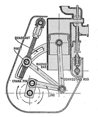
A straight-line mechanism is a mechanism that converts any type of rotary or angular motion to perfect or near-perfect straight-line motion, or vice versa. Straight-line motion is linear motion of definite length or "stroke", every forward stroke being followed by a return stroke, giving reciprocating motion. The first such mechanism, patented in 1784 by James Watt, produced approximate straight-line motion, referred to by Watt as parallel motion.

Robotics is the branch of technology that deals with the design, construction, operation, structural disposition, manufacture and application of robots. Robotics is related to the sciences of electronics, engineering, mechanics, and software.

In engineering, a mechanism is a device that transforms input forces and movement into a desired set of output forces and movement. Mechanisms generally consist of moving components which may include Gears and gear trains; Belts and chain drives; cams and followers; Linkages; Friction devices, such as brakes or clutches; Structural components such as a frame, fasteners, bearings, springs, or lubricants; Various machine elements, such as splines, pins, or keys.
The following outline is provided as an overview of and topical guide to robotics:

Jansen's linkage is a planar leg mechanism designed by the kinetic sculptor Theo Jansen to generate a smooth walking motion. Jansen has used his mechanism in a variety of kinetic sculptures which are known as Strandbeesten. Jansen's linkage bears artistic as well as mechanical merit for its simulation of organic walking motion using a simple rotary input. These leg mechanisms have applications in mobile robotics and in gait analysis.
Kinematics equations are the constraint equations of a mechanical system such as a robot manipulator that define how input movement at one or more joints specifies the configuration of the device, in order to achieve a task position or end-effector location. Kinematics equations are used to analyze and design articulated systems ranging from four-bar linkages to serial and parallel robots.

A leg mechanism is a mechanical system designed to provide a propulsive force by intermittent frictional contact with the ground. This is in contrast with wheels or continuous tracks which are intended to maintain continuous frictional contact with the ground. Mechanical legs are linkages that can have one or more actuators, and can perform simple planar or complex motion. Compared to a wheel, a leg mechanism is potentially better fitted to uneven terrain, as it can step over obstacles.
In mechanical engineering, kinematic synthesis determines the size and configuration of mechanisms that shape the flow of power through a mechanical system, or machine, to achieve a desired performance. The word synthesis refers to combining parts to form a whole. Hartenberg and Denavit describe kinematic synthesis as
...it is design, the creation of something new. Kinematically, it is the conversion of a motion idea into hardware.
In robotics, Cartesian parallel manipulators are manipulators that move a platform using parallel-connected kinematic linkages ('limbs') lined up with a Cartesian coordinate system. Multiple limbs connect the moving platform to a base. Each limb is driven by a linear actuator and the linear actuators are mutually perpendicular. The term 'parallel' here refers to the way that the kinematic linkages are put together, it does not connote geometrically parallel; i.e., equidistant lines.


