An industrial robot is a robot system used for manufacturing. Industrial robots are automated, programmable and capable of movement on three or more axes.
In classical mechanics, the parameters that define the configuration of a system are called generalized coordinates, and the space defined by these coordinates is called the configuration space of the physical system. It is often the case that these parameters satisfy mathematical constraints, such that the set of actual configurations of the system is a manifold in the space of generalized coordinates. This manifold is called the configuration manifold of the system. Notice that this is a notion of "unrestricted" configuration space, i.e. in which different point particles may occupy the same position. In mathematics, in particular in topology, a notion of "restricted" configuration space is mostly used, in which the diagonals, representing "colliding" particles, are removed.

In computer animation and robotics, inverse kinematics is the mathematical process of calculating the variable joint parameters needed to place the end of a kinematic chain, such as a robot manipulator or animation character's skeleton, in a given position and orientation relative to the start of the chain. Given joint parameters, the position and orientation of the chain's end, e.g. the hand of the character or robot, can typically be calculated directly using multiple applications of trigonometric formulas, a process known as forward kinematics. However, the reverse operation is, in general, much more challenging.
In the engineering field of robotics, an arm solution is a set of calculations that allow the real-time computation of the control commands needed to place the end of a robotic arm at a desired position and orientation in space.

A Cartesian coordinate robot is an industrial robot whose three principal axes of control are linear and are at right angles to each other. The three sliding joints correspond to moving the wrist up-down, in-out, back-forth. Among other advantages, this mechanical arrangement simplifies the robot control arm solution. It has high reliability and precision when operating in three-dimensional space. As a robot coordinate system, it is also effective for horizontal travel and for stacking bins.
Robot kinematics applies geometry to the study of the movement of multi-degree of freedom kinematic chains that form the structure of robotic systems. The emphasis on geometry means that the links of the robot are modeled as rigid bodies and its joints are assumed to provide pure rotation or translation.
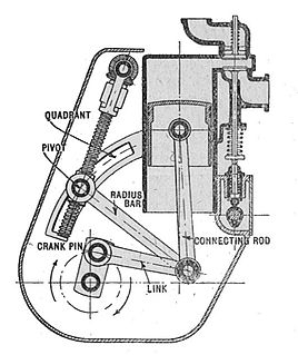
A mechanical linkage is an assembly of systems connected to manage forces and movement. The movement of a body, or link, is studied using geometry so the link is considered to be rigid. The connections between links are modeled as providing ideal movement, pure rotation or sliding for example, and are called joints. A linkage modeled as a network of rigid links and ideal joints is called a kinematic chain.
In physics, the degrees of freedom (DOF) of a mechanical system is the number of independent parameters that define its configuration or state. It is important in the analysis of systems of bodies in mechanical engineering, structural engineering, aerospace engineering, robotics, and other fields.

Six degrees of freedom (6DOF) refers to the freedom of movement of a rigid body in three-dimensional space. Specifically, the body is free to change position as forward/backward (surge), up/down (heave), left/right (sway) translation in three perpendicular axes, combined with changes in orientation through rotation about three perpendicular axes, often termed yaw, pitch, and roll. Three degrees of freedom (3DOF), a term often used in the context of virtual reality, refers to tracking of rotational motion only: pitch, yaw, and roll.

A delta robot is a type of parallel robot that consists of three arms connected to universal joints at the base. The key design feature is the use of parallelograms in the arms, which maintains the orientation of the end effector. In contrast, Stewart platform can change the orientation of its end effector.

A parallel manipulator is a mechanical system that uses several computer-controlled serial chains to support a single platform, or end-effector. Perhaps, the best known parallel manipulator is formed from six linear actuators that support a movable base for devices such as flight simulators. This device is called a Stewart platform or the Gough-Stewart platform in recognition of the engineers who first designed and used them.

Forward kinematics refers to the use of the kinematic equations of a robot to compute the position of the end-effector from specified values for the joint parameters.
In classical mechanics, a kinematic pair is a connection between two physical objects that imposes constraints on their relative movement (kinematics). German engineer Franz Reuleaux introduced the kinematic pair as a new approach to the study of machines that provided an advance over the motion of elements consisting of simple machines.

In mechanical engineering, a kinematic chain is an assembly of rigid bodies connected by joints to provide constrained motion that is the mathematical model for a mechanical system. As in the familiar use of the word chain, the rigid bodies, or links, are constrained by their connections to other links. An example is the simple open chain formed by links connected in series, like the usual chain, which is the kinematic model for a typical robot manipulator.

A robotic arm is a type of mechanical arm, usually programmable, with similar functions to a human arm; the arm may be the sum total of the mechanism or may be part of a more complex robot. The links of such a manipulator are connected by joints allowing either rotational motion or translational (linear) displacement. The links of the manipulator can be considered to form a kinematic chain. The terminus of the kinematic chain of the manipulator is called the end effector and it is analogous to the human hand. However, the term "robotic hand" as a synonym of the robotic arm is often proscribed.

321 kinematic structure is a design method for robotic arms, invented by Donald L. Pieper and used in most commercially produced robotic arms. The inverse kinematics of serial manipulators with six revolute joints, and with three consecutive joints intersecting, can be solved in closed form, i.e. a set of equations can be written that give the joint positions required to place the end of the arm in a particular position and orientation. An arm design that does not follow these design rules typically requires an iterative algorithm to solve the inverse kinematics problem.
There are many conventions used in the robotics research field. This article summarises these conventions.
The product of exponentials (POE) method is a robotics convention for mapping the links of a spatial kinematic chain. It is an alternative to Denavit–Hartenberg parameterization. While the latter method uses the minimal number of parameters to represent joint motions, the former method has a number of advantages: uniform treatment of prismatic and revolute joints, definition of only two reference frames, and an easy geometric interpretation from the use of screw axes for each joint.

A five-bar linkage is a two degree-of-freedom mechanism that is constructed from five links that are connected together in a closed chain. All links are connected to each other by five joints in series forming a loop. One of the links is the ground or base. This configuration is also called a pantograph, however, it is not to be confused with the parallelogram copying linkage pantograph.
In robotics, Cartesian parallel manipulators are manipulators that move a platform using parallel-connected kinematic linkages (`limbs') lined up with a Cartesian coordinate system. Multiple limbs connect the moving platform to a base. Each limb is driven by a linear actuator and the linear actuators are mutually perpendicular. The term `parallel' here refers to the way that the kinematic linkages are put together, it does not connote geometrically parallel; i.e., equidistant lines.


