The HVDC Inter-Island link is a 610km (380mi) long, 1200 MWhigh-voltage direct current (HVDC) transmission system connecting the electricity networks of the North Island and South Island of New Zealand together. It is commonly referred to as the Cook Strait cable in the media and in press releases,[1] although the link is much longer than its Cook Strait section. The link is owned and operated by state-owned transmission company Transpower New Zealand.
The HVDC link first became operational in April 1965 to primarily transport electricity from the generation-rich South Island to the more populous North Island. The link originally was a bipolar 600MW link with mercury arc valves, until the original equipment was paralleled onto a single pole (Pole 1) in 1992, and a new thyristor-based pole (Pole 2) was constructed alongside it, increasing the link's capacity to 1040MW. The ageing Pole 1 was fully decommissioned effective 1 August 2012, and a replacement thyristor-based pole, Pole 3, was commissioned on 29 May 2013,[2] restoring the DC link to a bipolar 1200MW configuration.
Rationale for the link
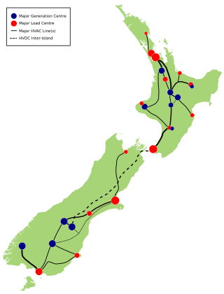
A map of the major power transmission lines in New Zealand, with the HVDC Inter-Island link being marked with a dashed black line.
The HVDC link is an important component of the transmission system in New Zealand. It connects the transmission grids of the two islands, and is used as an energy-balancing system, helping to match energy availability and demand in the two islands.
The two islands are geographically different – the South Island is 33 percent larger than the North Island in land area (151,000km2 vs 114,000km2), but the North Island has over three times the population of the South Island (4.00 million vs 1.23 million).[3] As a consequence, the North Island has a substantially larger energy demand. However, the South Island uses more electricity per capita due to its cooler climate and the presence of the Tiwai Point Aluminium Smelter, which at a peak demand of 640MW is New Zealand's largest single electricity user. In 2011, around 37.1% of the total electricity generated was consumed in the South Island, while 62.9% was consumed in the North Island. South Island generation accounted for 40.9% of the nation's electricity in 2011, nearly all (97%) from hydroelectricity, while the North Island generated the remaining 59.1% from a mixture of mainly hydroelectric, natural gas, and geothermal generation, plus smaller amount of coal and wind generation.[4]
If all currently commissioned generation is available, both islands have enough generating capacity at peak times, without the connection between the two islands.[5] However, the HVDC link provides benefits for customers in both the South Island and North Island:
The link provides the South Island consumers with access to the North Island's thermal generation resources that can support the South Island demand during times of low water storage levels and low inflows to South Island hydroelectric lakes.
The link provides North Island consumers with access to the South Island's large hydro generation resources that can support the North Island demand at times of peak load.
The link plays an important role in the New Zealand electricity market, and allows North and South Island generators to compete with each other, therefore driving wholesale electricity prices down.[6]
The inter-island transmission system was designed as a high-voltage direct current (HVDC) system, despite the cost of the conversion from alternating current (AC) to direct current (DC) and back again, to suit the requirements of a long transmission line and a sea crossing. The link crosses Cook Strait, between the two islands, using submarine power cables laid along the sea floor. HVDC is more suitable than AC for transmission over long distances, and particularly where submarine cable transmission is required, because it is typically more economic, and has lower energy losses, despite the high costs of the AC/DC conversion process.[7]
Route
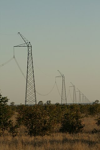
HVDC transmission line tower in coastal Marlborough region
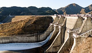
The HVDC Inter Island link starts at two converter stations located adjacent to Benmore Hydroelectric Power Station in the Waitaki Valley. Electricity is taken from the main Benmore switchyard, which interconnects the Benmore generators and rest of the South Island transmission grid, at 220kV via tie-lines across the Benmore tailrace. The AC power is converted at the stations to ±350kV HVDC for transmission
The HVDC transmission line crosses the Benmore power station tailrace and takes a route along the eastern side of the dam. The line continues north along the eastern shore of Lake Benmore, before turning north-east and then east to meet the Christchurch to Twizel HVAC line. Crossing State Highway 8 south of Fairlie, the line then turns northeast, passing between Fairlie and Geraldine. North of Geraldine to Oxford, the HVDC line broadly follows the Inland Scenic Route tourist highway through the inland Canterbury Plains, passing close to the towns of Methven, Sheffield and Oxford, before continuing northeast towards Waipara.
The HVDC line passes through Weka Pass into the Amuri district, travelling north through the region, west of Culverden, to Hanmer Springs. From here, the line turns north-east and travels through Molesworth Station into Marlborough and down the Awatere River valley, before turning north to meet State Highway 1 through the Dashwood and Weld Passes. The line travels east of Blenheim, meeting the eastern coast of the island at Cloudy Bay, and travelling up the coast into the Marlborough Sounds. The line turns east and then south-east around Port Underwood, before crossing to Fighting Bay on the coast, where the South Island cable terminal is located.
At this physical location, the lines connects to three undersea cables taking electricity underneath Cook Strait. As of August 2012[update], Pole 2 uses two of these cables, with the third cable unused waiting the commissioning of Pole 3. The cables initially head south out of Fighting Bay, before turning east towards the North Island, and then turning northeast towards the North Island cable terminal at Oteranga Bay.
From Oteranga Bay, the land-based North Island transmission line travels northeast through Mākara just west of Johnsonville. West of Ngaio, the electrode line from the North Island shore electrode at Te Hikowhenua, north of Mākara Beach, merges with the main transmission line towers for the final connection to the North Island converter station. The line turns eastwards around Churton Park, crossing to Horokiwi before turning north-east and passing through Belmont Regional Park to Haywards in northern Lower Hutt, the site of the North Island static inverter plant.
At Haywards, two converter stations receive HVDC power at ±350kV, and convert it to alternating current at 220kV AC. From here, the power from the Inter Island link flows to the main Haywards HVAC substation, where it is distributed to the Wellington urban area, or is transmitted north to the rest of the North Island grid.
Technical description
Simplified schematic of New Zealand HVDC scheme
The New Zealand Inter-Island HVDC link is a long distance bipolar HVDC "Classic" transmission scheme that uses overhead lines and submarine cables to connect between the South and North Islands. It uses thyristor-based line-commutated converters at each end of the link for rectifying and inverting between AC and DC. The link includes ground electrode stations that enable the use of earth return current. This permits operation with unbalanced current between the two poles, and monopolar operation when one pole is out of service.
Converter stations
The converter stations for each pole, at each end of the link include:
converter valve hall, cooling system and control building
converter transformers
220kV AC switchyard equipment and connections
220kV AC harmonic filters
350kV DC switchyard equipment, including DC smoothing reactor
The converter valves are twelve-pulse converters, arranged as three water-cooled quadrivalve assemblies. Both Pole 2 and Pole 3 use a design that suspends the quadrivalves from the roof of the valve hall. This provides superior seismic performance compared with a ground mounted arrangement, especially in New Zealand's highly seismic environment.[8] There are three single-phase converter transformers for each converter valve (plus one spare transformer), and each transformer has two secondary windings connected to the valve.
Each converter station requires power factor correction equipment to generate reactive power for the converters and provide voltage support to the surrounding AC grid. At the Benmore converter station, reactive power is provided by the generators at Benmore Dam. At the Haywards converter station, reactive power and power factor correction is provided by eight synchronous condensers, two shunt capacitors, two shunt reactors, and one static synchronous compensator (STATCOM).[9]
Details of the converter station equipment and ratings are given in the table below:[10]
The three submarine power cables installed in 1991 are each rated to carry 1430A continuously at 350kV operating voltage. They are constructed with a compacted multi-strand copper conductor as a central core, with mass-impregnated paper insulation surrounded by a lead sheath. Two layers of galvanised steel wire armour provides strength and mechanical protection. The outer layer of the cable is a serving made from polypropylene rope and the outer diameter is approximately 130mm. The cables have a 30-minute overload capacity of 1600A.[8]
To ensure security of the link's submarine power cables, a seven-kilometre wide Cable Protection Zone (CPZ) is enforced where the cables cross Cook Strait. Vessels are not permitted to anchor or fish in this area, and the area is routinely patrolled by sea and air. Anyone found anchoring or fishing in the area is liable for fines up to $100,000 and forfeiture of their vessel – more if a cable is subsequently damaged.[11]
HVDC transmission line
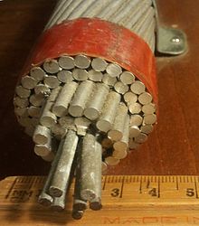
Sample cross-section of HVDC line conductorLabel on line conductor sample (original rating ±250kV)
The transmission line was designed and built by the New Zealand Electricity Department, and was completed in January 1965. The original construction of the line included the erection of 1623 steel lattice towers. In some South Island sections, the line reaches an altitude of 1280metres. The longest span is 1119m, near Port Underwood, close to the Fighting Bay cable terminal station.
The line was originally designed for operation at ±250kV. During the DC Hybrid link project of 1989 to 1992, the transmission line was reinsulated with DC fog type porcelain insulator units, to enable operation at 350kV. There are 15 units per insulator string in the inland parts of the route, and 33 units per insulator string in the coastal parts of the route that are exposed to salt condensation. The insulator strings in the coastal portions are around 5m long.[8]
The transmission line insulators support a pair of ACSR conductors on each side of the towers. The conductors are each 39.4mm in diameter, and are spaced 432mm apart.[12]
The HVDC line has a continuous overhead earthwire for lightning protection, except for a 21km section at the Haywards end, where the line is shielded by the electrode line conductors. A 13km section of the North Island HVDC line uses an overhead earthwire containing a fibre optic core (OPGW), and a further 169km section of OPGW is installed the South Island line.[8]
About 20 new towers were constructed in 1992 to reroute the HVDC line north of Johnsonville to make way for new residential development. This was known as the Churton Park deviation.[13]
Around 92.5 percent (1503) of the towers on the line in 2010 were identified as being original, with the remaining towers having been replaced due to line deviations, collapse, or corrosion.
Following the DC Hybrid Link project, the line was rated to carry 2000amperes continuously on each pole, at an operating voltage of 350kV HVDC.
Earth electrode stations
The connection between the North Island converter station and earth uses a shore electrode station located at Te Hikowhenua, approximately 25km from Haywards. Following upgrades carried out during the DC Hybrid Link project, the electrode station is capable of carrying 2400A continuously. Forty electrode cells are buried along an 800m length of a stony beach. Each electrode cell consists of a high silicon-chromium iron electrode, suspended in a vertical porous concrete cylinder. The cells are surrounded by selected and graded stones and geotextile layers to allow seawater ingress, but prevent the buildup of silt. The electrode to ground resistance is 0.122Ω.[8]
The South Island ground electrode station is located at Bog Roy, 7.6km from Benmore. It comprises buried electrode arms arranged in a star configuration over a site of approximately 1km2. Each electrode arm is a 40mm mild steel rod buried in a coke bed of around 0.26m2 cross sectional area, in a 1.5m deep trench. The electrode to ground resistance is 0.35Ω.[8] A small transmission line carries a twin conductor electrode circuit from the Benmore converter station site to the South Island land electrode at Bog Roy, which in conjunction with the shore electrode in the North Island, allows one pole to operate using earth return when the other pole is out of service.
Transmission faults and outages
Like all transmission systems, the HVDC Inter-Island link is not immune to failures. The importance of the link means that an unplanned outage can have major implications for the entire New Zealand electricity system, potentially causing nationwide frequency deviation (underfrequency in the receiving island, overfrequency in the other island), electricity shortages in the receiving island, and a spike in wholesale electricity prices. The most catastrophic situation is a simultaneous bipole outage at high transfer when there is low to medium generation in the receiving island—instantaneous reserve generation and load shedding systems in the receiving island would not be able to come online fast enough to prevent the frequency dropping, resulting in cascading failure and outage of the entire receiving island.[14]
Planned outages of the link are required occasionally to carry out maintenance that is not possible while the system is live. Maintenance outages are planned well in advance to minimise the effects – they are usually carried out in summer when national electricity demand is at its lowest, and on only one pole at a time, with the other pole remaining in operation providing half of the full two-pole capacity, using the earth electrodes providing a path for return current through the ground.
Notable faults and outages on the HVDC Inter-Island link:
1973 – an electrical fault occurred in the shore joint of Cable 1 at Fighting Bay.[15]
August 1975 – A strong wind storm caused a string of seven transmission towers to collapse and damage the line. The link took five days to repair.[15]
1976 – A fault occurred at the Cable 1 undersea joint, 15.5km from the South Island end at a depth of 120metres. The joint was repaired in 1977.[15]
1980 – Cable 3 failed at the Fighting Bay shore joint.[15]
1981 – A gas leak on Cable 1 occurred at Oteranga Bay. It was repaired in the 1982/83 summer.[15]
1988 – Cable 2's Oteranga Bay end joint exploded, spilling insulating oil into the switchyard.[15]
2004 – In January, three HVDC towers collapsed as a result of extreme winds, and in August the line voltage had to be reduced for long periods because of insulation flashovers caused by severe salt pollution at the cable station at Oteranga Bay. In October, a fault occurred in one of three Cook Strait cables that reduced the Pole 1 capacity from 540MW to 386MW. Repairs took almost six months.[16]
19 June 2006 – The link experienced an unplanned outage just before the evening peak period on one of the coldest days of the year. With four North Island power stations out for service and an outage of Tauranga's ripple load control equipment, even with the reserve Whirinaki Power Station called upon, the North Island experienced electricity shortages and Transpower subsequently declared a nationwide Grid Emergency at 5:34pm. The link was restored shortly after the emergency was declared.[15]
28 August 2008 – A transmission tower in the Marlborough Sounds was found buckled after its foundations slipped. The tower was reinforced with steel guy ropes until it could be replaced, as the link couldn't be shut down without causing widespread power shortages in the South Island.[17]
12 November 2013 – During the commissioning of the new two-pole control systems, a test to assess the control's response to a trip on a 220kV line out of Haywards during high north flow caused three filter banks at Benmore to trip off the grid. The HVDC controls automatically cut northbound transfer from 1000MW to 140MW, causing automatic underfrequency load shedding (AUFLS) systems to deploy in the North Island, and blacking out thousands of customers. A software bug was found to be the cause of the filter bank trips.
17 August 2021 - The HVDC transmission line failed in the Weka Pass region, leading to conductors of the Pole 2 circuit falling across State Highway 7. Transpower issued a Grid Emergency Notice later in the day, advising that there was insufficient generation and transmission capacity to meet the forecast evening peak load in the North Island. Severe weather conditions delayed the repair and the return to service until 26 August.[18][19][20]
The original link
Mercury arc valves in valve hall at Haywards.
Planning
The initial vision for electricity transmission between the South and North Islands was developed by Bill Latta, the Chief Engineer of the State Hydroelectric Department. In 1950, he prepared a paper on the future of the North Island's electric power supply and he drew attention to the projected growth of the load and the limited potential for more hydroelectric generation development on the North Island. Latta's vision was to build more hydroelectric generating capacity in the South Island, where there was still significant opportunities for new schemes, and to transmit the power to the southern half of the North Island to meet the increasing demand.[12]
In 1951, the cable manufacturing company British Insulated Callender's Cables (BICC) advised the State Hydroelectric Department that a cable crossing of Cook Strait was possible, but difficult, since there was no precedent for installing power cables in such difficult marine conditions.[21]
The development of high power mercury arc valve converters in the 1950s led to the development of several HVDC transmission schemes in other countries. This demonstrated that a long distance, high power HVDC transmission scheme was feasible in principle.
In 1956, the Government appointed BICC to undertake detailed investigations of the practicality and cost of a Cook Strait cable crossing. In December of that year, BICC reported that the project was "thoroughly practicable".[15]
In parallel with the technical investigations for cables underneath Cook Strait, the Minister responsible for the State Hydroelectric Department appointed a committee of key stakeholders to report on the options for power supply to New Zealand as a whole, not just the North Island. In 1957, the committee recommended that work commence on a large hydroelectric power station on the Waitaki River at Benmore, and that approval in principle should be given for linking the North and South Island's power systems.
Recommendations were also received from the Swedish company ASEA (today part of the ABB), about the technical aspects of the HVDC converter stations.
The unique planning considerations for the overall proposal included:[12]
The hydroelectric generators at Benmore would need to be capable of absorbing the harmonic currents that would be created by the operation of the mercury arc converters.
The Benmore generators were proposed to have an operating voltage of 16 kV, which was a new high for New Zealand hydroelectric generators at the time.
The 16 kV circuit breakers required at Benmore would be state of the art.
The mercury arc valves would be larger than any previously constructed, and would require water-cooled cathodes.
The overhead HVDC transmission line would be one of the longest and most difficult built in New Zealand up to that time.
The Cook Strait submarine cables would have to be specially designed for the seabed and tidal conditions, and require special armouring at the Oteranga Bay end, of a kind that had not been used before.
In 1958, BICC laid two 0.8km trial lengths of cable off Oteranga Bay in Cook Strait to demonstrate their ability to resist the abrasion, bending and vibration caused by conditions on the seabed. These trial lengths were recovered and inspected in 1960, and by October that year, BICC reported that the trial had been successful and that the prototype cable would provide good service underneath Cook Strait.[12]
In the period 1958 to 1960, some differing views were offered to Government about the most appropriate power developments for the country as a whole, and there were reservations about the risks involved in the planned Cook Strait cable crossing.[21]
However, in March 1961, against a background of increasing urgency in meeting the forecast demand, the Government approved the project. A NZ£6.5 million contract was placed with ASEA for the design, manufacture, installation and commissioning of the converter plant at Benmore and Haywards, and a NZ£2.75 million contract was placed with BICC for the manufacture, delivery, laying and testing of the Cook Strait submarine cables.[12]
Construction
The HVDC inter-island link was designed and built between 1961 and 1965 for the New Zealand Electricity Department. The major equipment suppliers were ASEA and British Insulated Callender's Cables.[12] The original Cook Strait cables were installed in 1964, from the cable laying ship Photinia.[22]
When it was completed, the New Zealand HVDC link was the world's longest HVDC transmission scheme, with the highest power rating, and the largest undersea power cables.[23] The terminal stations at each end of HVDC link used large mercury-arcrectifiers and inverters – 1960s technology – to convert between AC and DC. The South Island converter station was established at the Benmore hydroelectric power station in the Waitaki Valley. The North Island converter station was built at Haywards in the Hutt Valley near Wellington.
The HVDC transmission line that connects Benmore and Haywards converter stations has an overall length of 610 kilometres. The overhead transmission line is supported by 1649 transmission towers and has a total route length of 570km. The submarine cables underneath Cook Strait are 40km long.[24]
Until it was upgraded in 1993, the HVDC Inter-Island link had normal operating voltages of ±250kV, and a maximum power transmission capacity of about 600MW.
The HVDC link was originally designed to transfer power northwards from Benmore to Haywards. In 1976, the control system of the original scheme was modified to allow power to be sent in the reverse direction, from Haywards to Benmore.[12]
Engineering heritage status
The original HVDC link was recognised as a significant part of New Zealand's engineering heritage by the Institution of Professional Engineers New Zealand, (now Engineering New Zealand), during the "Engineering to 1990" project, which helped to celebrate the country's sesquicentenary in 1990.[25]
The Hybrid Upgrade Project
Haywards Pole 2 thyristor valve, during maintenance shutdown.
In 1987, the Electricity Corporation of New Zealand began investigations to find the best means of upgrading the inter-island link. A hybrid upgrade was chosen over total replacement, for economic reasons. The term "hybrid" was adopted because the increase in capacity was to be obtained through a combination of voltage and current upgrades. The upgrade project involved continued use of the existing mercury arc valve converter equipment alongside new solid-state thyristor converter stations. The scope of work included:[15]
Providing three new HVDC submarine cables underneath Cook Strait, to supplement and ultimately replace the original cables. Each new cable was rated at 350kV, 1430A, giving a maximum power capacity of 500MW per cable. The three new power cables were installed in 1991 by the cable laying vessel Skagerrak.[26]
New cable terminal stations at Fighting Bay and Oteranga Bay
The existing mercury arc valve converters at each end of the link were reconfigured to operate in parallel at each station (they had previously operated with opposite electrical polarity). They were redesignated as Pole 1.
The operating voltage of the mercury arc valve converters was increased from the original 250kV to 270kV
New HVDC thyristor converter stations were added at each end of the link. These had an operating voltage of 350kV, and were designated as Pole 2.
The reinsulating of the entire HVDC overhead transmission line to increase its rating to 350kV. Work on transmission structures and conductors was also carried out to ensure that the line conductors could operate at up to 2000A on each Pole.
The Pole 2 converter stations and new submarine cables were commissioned in March 1991.
The upgrade brought the total converter station capacity to 1348MW (648+700MW), however the link was restricted to 1240MW due to the overhead transmission line rating's restricting Pole 1's operating capacity to 540MW. After the retirement of the last of the original submarine cables, the overall HVDC link transfer capability was restricted further to 1040MW due to the single Pole 2 cable underneath Cook Strait.[12]
In its Asset Management Plan 2018, Transpower indicated that in the regulatory period 2020-2025 it planned significant expenditure to extend the life or replace ageing equipment in the Pole 2 converter stations that is near the end of its original 30-year design life. [27]
Decommissioning of Pole 1
On 21 September 2007, the original Pole 1 mercury-arc converter stations were shut down "indefinitely". However, in December 2007, Transpower announced that one-half of the capacity of Pole 1 would be returned to "warm standby" service before the winter of 2008 in order to meet the demand for power in the North Island if needed. The remaining half-pole equipment of Pole 1 was to be decommissioned.[28]
Transpower also announced in November 2007 that by December 2007, it would increase the south to north power transmission capacity of Pole 2 from 500MW to 700MW. This was done by reconfiguring the three operational submarine cables. One of the two cables previously connected to Pole 1 was transferred to Pole 2.[29]
On 13 March 2008, Transpower announced that work had been completed to restore 50% of the capacity of Pole 1 to service at times when the demand for power on the North Island peaked.[30] Several mercury arc rectifiers were cannibalized from the Konti-Skan link between Denmark and Sweden for this restoration. The energy transfer on Pole 1 was strictly limited to the northbound direction, to reduce the stress and strain on the aging converter system.
In May 2009, Transpower placed the remaining capacity of Pole 1 back into service for a short period, at a limited capacity of 200MW, in response to a temporary loss of capacity on Pole 2.
The decommissioning of half of Pole 1 and the operational restrictions placed on the remaining Pole 1 capacity led to the HVDC link operating mostly in monopolar mode, using Pole 2 alone. In 2010, Transpower reported that continuous operation in monopolar mode has caused the HVDC link to act as a galvanic cell with the earth, causing Benmore's Bog Roy earth electrodes to erode as they acted as an anode, and causing the buildup of magnesium and calcium hydroxide deposits on Hayward's Te Hikowhenua shore electrodes as they acted as a cathode. Additional replacement and maintenance work was required.[24]
On 1 August 2012, Transpower decommissioned the remaining half of the Pole 1 mercury arc valve converter stations at Benmore and Haywards, after 47 years in service. The Inter Island link at the time was the last HVDC system in the world with mercury arc valve converters in operational service.[31]
The Pole 3 Project
In May 2008, Transpower submitted an investment proposal to the Electricity Commission for the replacement of the old mercury arc valve Pole 1 converter stations with new thyristor converter stations. In July 2008, the Electricity Commission announced its intention to approve the project.[32]
Lifting the roof of the Pole 3 valve hall into position at Benmore
This project involved the construction of new converter stations designated as Pole 3, to operate at +350 kV 700MW, matching the existing Pole 2 (−350 kV, 700MW). Site works on the $672million project were formally commenced on 19 April 2010, when Minister of Energy Gerry Brownlee turned the first sod. The new converter stations were to be commissioned by April 2012,[33] but in May 2011, Transpower announced that commissioning was delayed until December 2012 because of difficulties being experienced by the manufacturer. [34]
Work involved in replacing Pole 1 with the new Pole 3 converter stations included:[6]
New valve halls adjacent to the Pole 2 valve halls at both Benmore and Haywards, each containing the thyristors converters
New transformers connecting the valve halls to the 220kV buses at both Benmore and Haywards
Connecting the Pole 3 thyristors to the existing Pole 1 lines at both Benmore and Haywards
Connecting the Pole 3 thyristors to the existing electrode lines at both Benmore and Haywards
Switching the number 5 Cook Strait cable from Pole 2 back to the Pole 1/3.
New 220kV filters on the 220kV buses at both Benmore and Haywards
New transformers connecting the four synchronous condensers C7 to C10 to the 110kV bus at Haywards
New 5th and 7th harmonic filters connecting to the 110kV bus at Haywards.
Removal of the existing converter transformers connecting the Pole 1 mercury arc valves and two of the synchronous condensers to the 110kV bus at Haywards.
Removal of all remaining mercury arc valve Pole 1 equipment at both Benmore and Haywards.
The decommissioning of Pole 1 was scheduled for July 2012, allowing works to switch the existing lines over Pole 3 to occur, and to allow testing of the new pole to occur during the summer months where electricity demand and therefore inter-island electricity transfer is low. The new Pole 3 was able to operate at 700MW from commissioning, but due to inadequate voltage support at the Haywards end of the link, Pole 2 and 3 combined transfer was limited to 1000MW. After the commissioning of a new static synchronous compensator (STATCOM) at Haywards in January 2014, Pole 3 was able to operate at its full capacity with Pole 2 in operation (1200MW total transfer).[35]
Pole 2 control system replacement
Pole 2 was commissioned in 1992 with HVDC control systems using late 1980s technology. After 20 years in service, the control systems are nearing the end of their useful life, are technologically obsolete, and are incompatible with the new Pole 3 control systems, making bipole control impossible.
In late 2013, Transpower took Pole 2 out of service for four weeks to allow the control systems to be replaced with new systems identical to those used in Pole 3, and to install a new bipole control system to control both poles. This was followed by three months of testing the new control systems. Pole 3 continued to operate during the outage and most of the testing in a monopolar configuration with the earth electrodes.
Other associated works
Line maintenance
During the time that Pole 1 was removed from service for replacement with Pole 3, maintenance and remedial work was undertaken on some sections of the transmission line. Work included:[35]
Replacing around 100 transmission towers in the South Island to fix clearance issues
Replacing some conductor lengths in the North Island as they approach the end of their useful life
Reinforcing some North Island transmission towers.
Benmore generator transformers
The original design of the inter-island link at Benmore was integrated with the design of the 540MW Benmore hydroelectric power station. The 16kV generator busbars in the power station were the point of connection between the HVDC link and the South Island grid. The power from the six Benmore generators could flow directly from the 16kV busbars to the HVDC link via converter transformers, with the interconnecting transformers connecting to the Benmore 220kV busbar to export or import electricity from the rest of the South Island. The design of the power station was optimised with the HVDC link, and the interconnecting transformers were designed with a significantly lower rating than the maximum output of the Benmore generators, because so much of the generator output power would normally flow to the HVDC link.
Following Transpower's decommissioning of the original Pole 1 equipment, there was no longer any direct connection between the generator 16kV busbars and the HVDC link, and the limited capacity of the Benmore interconnecting transformers would have constrained the maximum output of the station. In co-ordination with the Transpower programme for decommissioning of the Pole 1 equipment, Benmore owner Meridian Energy replaced the interconnecting transformers with new generator transformers. The six generators were reconnected to the 220kV national grid via six new generator circuit breakers and three 220/16/16kV three winding transformers. The new transformers each connect two generators, via two 16kV secondary windings.[36][37]
Planned upgrades
Cook Strait cables
In 2024, the Commerce Commission approved a proposal from Transpower to upgrade the capacity of the HVDC link by adding a fourth Cook Strait cable and additional reactive support at Haywards. The new investment would enable an increase in maximum HVDC capacity to 1,400MW. The upgrade was approved as a contingency, where the timing would depend upon triggers such as the exit of the aluminium smelter from Tiwai Point, developments in the load and generation forecasts, and Transpower demonstrating a net positive market benefit from the investment.[38][39]
Transpower stated that the existing submarine cables would reach end-of-life in the early 2030s and would cost around $400 million to replace.[38]
A high-voltage direct current (HVDC) electric power transmission system uses direct current (DC) for electric power transmission, in contrast with the more common alternating current (AC) transmission systems.
Benmore Dam is the largest dam within the Waitaki power scheme, located in the Canterbury Region of New Zealand's South Island. There are eight other power stations in the Waitaki Power Scheme.
The Baltic Cable is a monopolar HVDC power line running beneath the Baltic Sea that interconnects the electric power grids of Germany and Sweden. Its maximum transmission power is 600 megawatts (MW).
The HVDC Volgograd–Donbass is a 475 kilometres (295 mi) long bipolar ±400 kV high voltage direct current powerline used for transmitting electric power from Volga Hydroelectric Station at Volgograd in Russia to Donbas in eastern Ukraine and vice versa.
The HVDC Cross-Channel is the 73-kilometre-long (45 mi) high-voltage direct current (HVDC) interconnector that has operated since 1986 under the English Channel between the continental European grid at Bonningues-lès-Calais and the British electricity grid at Sellindge. The cable is also known as IFA, and should not be confused with the new IFA-2, another interconnect with France that is three times as long but only half as powerful.
The Pacific DC Intertie is an electric power transmission line that transmits electricity from the Pacific Northwest to the Los Angeles area using high voltage direct current (HVDC). The line capacity is 3.1 gigawatts, which is enough to serve two to three million Los Angeles households and represents almost half of the Los Angeles Department of Water and Power (LADWP) electrical system's peak capacity.
The Nelson River DC Transmission System, also known as the Manitoba Bipole, is an electric power transmission system of three high voltage, direct current lines in Manitoba, Canada, operated by Manitoba Hydro as part of the Nelson River Hydroelectric Project. It is now recorded on the list of IEEE Milestones in electrical engineering. Several records have been broken by successive phases of the project, including the largest mercury-arc valves, the highest DC transmission voltage and the first use of water-cooled thyristor valves in HVDC.
HVDC Kingsnorth was a high-voltage direct-current (HVDC) transmission system connecting Kingsnorth in Kent to two sites in London. It was at one time the only application of the technology of high voltage direct current transmission for the supply of transformer stations in a city, and the first HVDC link to be embedded within an AC system, rather than interconnecting two asynchronous systems. It was also the first HVDC scheme to be equipped with self-tuning harmonic filters and to be controlled with a "Phase Locked Oscillator", a principle which subsequently became standard on all HVDC systems.
Cahora-Bassa is a separate bipolar HVDC power transmission line between the Cahora Bassa Hydroelectric Generation Station at the Cahora Bassa Dam in Mozambique, and Johannesburg, South Africa.
The Inga–Shaba EHVDC Intertie is a 1,700 kilometres (1,100 mi)-long high-voltage direct current overhead electric power transmission line in the Democratic Republic of Congo, linking the Inga hydroelectric complex at the mouth of the Congo River to mineral fields in Shaba (Katanga). It was primarily constructed by Morrison-Knudsen International, an American engineering company, with the converter equipment supplied by ASEA. Construction was completed in 1982 and it cost US$900 million. The scheme was, for many years, the longest HVDC line in the world.
An HVDC converter station is a specialised type of substation which forms the terminal equipment for a high-voltage direct current (HVDC) transmission line. It converts direct current to alternating current or the reverse. In addition to the converter, the station usually contains:
The HVDC Itaipu is a High-voltage direct current overhead line transmission system in Brazil from the Itaipu hydroelectric power plant to the region of São Paulo. The project consists of two ±600 kV bipoles, each with a rated power of 3150 MW, which transmit power generated at 50 Hz from the Paraguay side of the Itaipu Dam to the Ibiúna converter station near São Roque, São Paulo. The system was put in service in several steps between 1984 and 1987, and remains among the most important HVDC installations in the world.
Path 27, also called the Intermountain or the Southern Transmission System (STS), is a high-voltage direct current (HVDC) electrical transmission line running from the coal-fired Intermountain Power Plant near Delta, Utah, to the Adelanto Converter Station at Adelanto, California, in the Southwestern United States. It was installed by Asea, a company based in Sweden, and commercialized in July 1986. The system is designed to carry power generated at the power plant in Utah to areas throughout Southern California. It is owned and operated by the Intermountain Power Agency, a cooperative consisting of six Los Angeles-area cities, the largest member being the Los Angeles Department of Water and Power (LADWP), and 29 smaller Utah municipalities.
Haywards is a small hillside suburb in the Hutt Valley near Wellington, New Zealand. It is notable for its large electrical substation, which is the main switching point for the Wellington region, and the home of the North Island converter station for the HVDC Inter-Island, which links the North and South Island electricity networks together.
The electricity sector in New Zealand uses mainly renewable energy, such as hydropower, geothermal power and increasingly wind energy. As of 2021, the country generated 81.2% of its electricity from renewable sources. The strategy of electrification is being pursued to enhance the penetration of renewable energy sources and to reduce greenhouse gas (GHG) emissions across all sectors of the economy. In 2021, electricity consumption reached 40 terawatt-hours (TW⋅h), representing a 0.2% increase compared to the consumption levels in 2010.
The National Grid is the nationwide system of electric power transmission in New Zealand. The grid is owned, operated and maintained by Transpower New Zealand, a state-owned enterprise, although some lines are owned by local distribution companies and leased to Transpower. In total, the national grid contains 11,803 kilometres (7,334 mi) of high-voltage lines and 178 substations.
HVDC BorWin1 is the first HVDC facility in the world to be built for importing power from an offshore wind park to shore, and the first to use voltage source converters (VSC) in Germany. It connects the offshore wind park BARD Offshore 1 and other offshore wind farms in Germany near Borkum to the European power grid. The facility was built by ABB and has a capacity of 400 MW at a bipolar voltage of ±150 kV. HVDC BorWin1, which leads from BorWin Alpha Offshore Platform to Diele substation, consists of a 75 kilometres (47 mi) of underground and 125 kilometres (78 mi) of submarine cable.
Electricity Ashburton Limited, trading as EA Networks is a co-operatively-owned electricity distribution company, based in Ashburton, New Zealand.
The Xiangjiaba–Shanghai HVDC system is a ±800 kV, 6400 MW high-voltage direct current transmission system in China. The system was built to export hydro power from Xiangjiaba Dam in Sichuan province, to the major city of Shanghai. Built and owned by State Grid Corporation of China (SGCC), the system became the world’s largest-capacity HVDC system when it was completed in July 2010, although it has already been overtaken by the 7200 MW Jinping–Sunan HVDC scheme which was put into operation in December 2012. It also narrowly missed becoming the world’s first 800 kV HVDC line, with the first pole of the Yunnan–Guangdong project having been put into service 6 months earlier. It was also the world’s longest HVDC line when completed, although that record is also expected to be overtaken early in 2013 with the completion of the first bipole of the Rio Madeira project in Brazil.
HVDC BorWin2 is a high voltage direct current (HVDC) link built to transmit offshore wind power to the power grid of the German mainland. The project differs from most HVDC systems in that one of the two converter stations is built on a platform in the sea. Voltage-Sourced Converters are used and the total cable length is 200 km. The project was completed by the Siemens/ Prysmian consortium and handed over to its owner, TenneT, in January 2015, becoming the first such project to be completed.
1 2 3 4 5 6 O'Brien, M T; Fletcher, D E; Gleadow, J C (29 September 1993). Principal Features of the New Zealand DC Hybrid Link. Wellington: CIGRE. International Colloquium on High Voltage Direct Current and Flexible AC Power Transmission Systems.
1 2 Martin, John E, ed. (1998). People, Politics and Power Stations: Electric Power Generation in New Zealand 1880–1998 (Seconded.). Wellington: Bridget Williams Books Ltd and Electricity Corporation of New Zealand. p.356. ISBN0-908912-98-6.
This page is based on this Wikipedia article Text is available under the CC BY-SA 4.0 license; additional terms may apply. Images, videos and audio are available under their respective licenses.