High-leg delta (also known as wild-leg, stinger leg, bastard leg, high-leg, orange-leg, red-leg, dog-leg delta) is a type of electrical service connection for three-phase electric power installations. It is used when both single and three-phase power is desired to be supplied from a three phase transformer (or transformer bank). The three-phase power is connected in the delta configuration, and the center point of one phase is grounded. This creates both a split-phase single-phase supply (L1 or L2 to neutral on diagram at right) and three-phase (L1–L2–L3 at right). It is sometimes called orange leg because the L3 wire is required to be color-coded orange in the United States.[1] By convention, the high leg is usually set in the center (B phase) lug in the involved panel, regardless of the L1–L2–L3 designation at the transformer.
High-leg delta service is supplied in one of two ways. One is by a three-phase transformer (or three single-phase transformers), having four wires coming out of the secondary, the three phases, plus a neutral connected as a center-tap on one of the windings. Another method (the open delta configuration) requires two transformers. One transformer is connected to one phase of the overhead primary distribution circuit to provide the lighting side of the circuit (this will be the larger of the two transformers), and a second transformer is connected to another phase on the circuit and its secondary is connected to one side of the lighting transformer secondary, and the other side of this transformer is brought out as the high leg. The voltages between the three phases are the same in magnitude, however the voltage magnitudes between a particular phase and the neutral vary. The phase-to-neutral voltage of two of the phases will be half of the phase-to-phase voltage. The remaining phase-to-neutral voltage will be the phase-to-phase voltage. So if A–B, B–C and C–A are all 240volts, then A–N and C–N will both be 120volts, but B–N will be 208volts.
Other types of three-phase supplies are wye connections, ungrounded delta connections, or corner-grounded delta[2] (ghost leg configuration) connections. These connections do not supply split single-phase power, and do not have a high leg.
Explanation
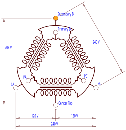
Phasor diagram showing 240V delta and center-tapped phase (a–c) creating two 120V pairs
Consider the low-voltage side of a 120/240V high leg delta connected transformer, where the b phase is the high leg. The line-to-line voltage magnitudes are all the same:
Because the winding between the a and c phases is center-tapped, the line-to-neutral voltages for these phases are as follows:
But the phase-neutral voltage for the b phase is different:
If the high leg is not used, the system acts like a split single-phase system, which is a common supply configuration in the United States.
Both three-phase and single split-phase power can be supplied from a single transformer bank.
Where the three-phase load is small relative to the total load, two individual transformers may be used instead of the three for a full delta or a three-phase transformer, thus providing a variety of voltages at a reduced cost. This is called open-delta high-leg, and has a reduced capacity relative to a full delta.[3][4][5]
Disadvantages
In cases where the single-phase load is much greater than the three-phase load, load balancing will be poor. Generally, these cases are identified by three transformers supplying the service, two of which are sized significantly smaller than the third, and the third larger transformer will be center tap grounded.
One of the phase-to-neutral voltage (usually phase B) is higher than the other two. The hazard of this is that if single phase loads are connected to the high leg (with the connecting person unaware that leg is higher voltage), excess voltage is supplied to that load. This can easily cause failure of the load.
Commonly there is a high-leg to neutral load limit when only two transformers are used.[6] One transformer manufacturer suggests that high-leg-to-neutral loading not exceed 5% of transformer capacity.[3]
Applications
It is often found in older and rural installations. This type of service is usually supplied using 240V line-to-line and 120V line-to-neutral. In some ways, the high leg delta service provides the best of both worlds: a line-to-line voltage that is higher than the usual 208V that most three-phase services have, and a line-to-neutral voltage (on two of the phases) sufficient for connecting appliances and lighting. Thus, large pieces of equipment will draw less current than with 208V, requiring smaller wire and breaker sizes. Lights and appliances requiring 120V can be connected to phases A and C without requiring an additional step-down transformer.
Watthour meters made for this application use two stators. One is the equivalent of a conventional single-phase, 3-wire meter typically used on residential services, connected across L1 and L2 (the 'lighting' portion of the service). The other stator is connected between L3 and the neutral (the wild-leg portion of the service).
It is also commonly used in installations in Japan. The distribution transformer output is 200 V line-to-line and 100 V line-to-neutral, while the high-leg to neutral voltage is 173 V. This provides 200 V for both three-phase and split-phase appliances.
Even when unmarked, it is generally easy to identify this type of system, because the B phase (circuits #3 and #4) and every third circuit afterwards will be either a three-pole breaker or a blank.
Current practice is to give separate services for single-phase and three-phase loads, e.g., 120V split-phase (lighting etc.) and 240V to 600V three-phase (for large motors). However, many jurisdictions forbid more than one class for a premises' service, and the choice may come down to 120/240V split-phase, 208V single-phase or three-phase (delta), 120/208V three-phase (wye), or 277/480V three-phase (wye) (or 347/600V three-phase (wye) in Canada).
This page is based on this Wikipedia article Text is available under the CC BY-SA 4.0 license; additional terms may apply. Images, videos and audio are available under their respective licenses.