Holzwarth gas turbine

Last updated
Holzwarth gas turbine
Holzwarth gasturbine prototype.jpg
A Holzwarth gas turbine prototype on the test bench at the Körting Brothers workshop in 1908
Classification Gas turbine
ApplicationElectrical power generation
Fuel source Coal gas, Blast furnace gas, Fuel oil or Coal dust
InventorHans Holzwarth
Invented1908
Total Units8 single-stage
2 dual-stage
Manufacturers Körting Brothers, Thyssen and Brown Boveri

The Holzwarth gas turbine is a form of explosion, or constant volume, gas turbine in which combustion takes place cyclically in a combustion chamber closed off by valves. The Holzwarth gas turbine is named after its developer Dr Hans Holzwarth (1877-1953) who designed several prototype engines used for testing and experimental service in Germany and Switzerland between 1908 and 1943. [1] [2] [3]

Contents

Design and Development

At the start of the 20th century, designers across Europe were working on the development of the constant flow gas turbine. The biggest problem for these early pioneers was the design of the compressor. The low efficiency of the turbo compressors available at the time meant that the compressor consumed all the energy supplied by the turbine. [4] The only large-scale gas turbine that ran during this period was the 1906 Armengaud-Lemale machine which could sustain its own compression but was too inefficient to do useful work. [5] Holzwarth's design avoided this problem by having combustion take place cyclically in combustion chambers closed off by valves. Since the pressure rise took place in the sealed combustion chamber there was no need for a compressor. [4]

Holzwarth developed the theoretical concept for his gas turbine from 1905, while he was an employee of Hooven-Owens-Rentschler in the USA. Holzwarth returned to Germany in 1908 where he designed and built a 25 hp (19 kW) machine while working for Thyssen & Co. This first machine was manufactured and tested at Körting's workshop in Hanover and is now on display at the Deutsches Museum in Munich. [1]

From 1909, Holzwarth worked with Brown, Boveri & Cie to build a market-ready 1,000 hp (746 kW) gas turbine however output and efficiency were below expectations and Brown Boveri withdrew from the project in 1912.

Holzwarth continued to work on his design while he was employed as chief engineer for gas turbines at Thyssen. In 1923 a prototype machine was delivered to the Prussian state railway where it was used to drive a 350 kW (469 hp) generator for several years. During this period tests were carried out using coal dust fuel which was found to burn acceptably in the combustion chamber but produced exhaust particles which damaged turbine blades. In 1927, Hans Holzwarth left Thyssen & Co and founded his own company, Holzwarth Gasturbinen GmbH. [1] [2]

In 1927 Aurel Stodola tested a 500 kW (671 hp) oil fired Holzwarth gas turbine and found that only 8% of the fuel's energy was transformed into mechanical energy. [1] Observations regarding the loss of waste heat to the cooling water led jacket led to the development, by Brown Boveri, of the commercially successful Velox boilers. [4] which in turn led to the development of the first modern industrial gas turbines. [4] [5]

From 1928, Holzwarth once again collaborated with Brown Boveri to build a version of his gas turbine with two sets of combustion chambers connected in series. These two-stage machines used a compressor driven by a stream turbine which was fed from the evaporation of water from the cooling water jacket. In 1933, a two-stage machine driving a 2,000 kW (2,682 hp) generator was installed at the Thyssen steelworks in Hamborn where it was initially operated with fuel oil and later with blast furnace gas. [4] [5]

The last Holzwarth gas turbine was an experimental 5,000 kW (6,705 hp) machine built by Brown Boveri's Mannheim factory in 1938 for the Hamborn steelworks. Fuel for combustion was blast-furnace gas compressed to about 6 bar (87 psi). The gas turbine had hydraulically operated valves working at 60-100 cycles per minute. The unit was only infrequently run and was not part of the steelwork's regular equipment. In 1943, the gas turbine was damaged during an Allied bombing raid after which no further test runs were made. After World War II ended, interest in the Holzwarth design declined and no further units were built. [2]

Operation

Diagrammatic section through one of the combustion chambers of a Holzwarth gas turbine Holzwarth combustion chamber.png
Diagrammatic section through one of the combustion chambers of a Holzwarth gas turbine

The explosion chamber (A) is filled intermittently with a rich mixture supplied from the gas chamber (C) and the air chamber (B). The mixture is ignited by spark after which the explosion of the mixture causes and increase in pressure throwing open the nozzle valve (F), allowing the compressed gases to flow through the nozzle (G) to the turbine wheel (H) on which the work is to be performed. While passing through the nozzle, the gases are expanded to the pressure of the exhaust (J). The nozzle valve (F) is kept open by fresh air throughout the expansion and subsequent scavenging and cooling. [6] [7]

When the expansion has been completed, air is blown, or drawn, in at a slight pressure through the valve (D). This scavenging air throws any residual gases left in the combustion chamber. through the nozzle, into the exhaust, after which the nozzle valve and the air valve (D) are positively closed. At this point the combustion chamber (A) is filled with pure, relatively cold air, into which the pure fuel (gas or atomized oil) is blown through the valve (E), thus forming the explosive mixture which is ignited by a spark. In order to make the impulses imparted to the turbine wheel more uniform, several combustion chambers working alternately are arranged in a circle around the turbine wheel (H). [6] [7]

In early Holzwarth machines, gas and air were supplied at a relatively low pressure around 0.1–1 bar (1–15 psi) [6] in later models a gas compressor was used to supply fuel at pressures up to 6 bar (87 psi). The gas compressor was driven by a steam turbine fed from the evaporation of water from the gas turbines cooling jacket which required the addition of a surface condenser package. [3]

The two Holzwarth gas turbines built by Brown Boveri after 1928 used two stages of combustion chambers and a “two stoke” version of the cycle where gas admission and exhaust took place simultaneously. [3] The first stage comprised the final charging of the combustion chamber, the explosion, the delivery of heat and energy in the steam generator and gas turbine. The second stage comprised the scavenging and the pre-charging. The residual exhaust gases escaped through an economiser to the atmosphere. [4]

Surviving example

This first prototype Holzwarth gas turbine is on display at the Deutsches Museum in Munich. [1]

Related Research Articles

<span class="mw-page-title-main">Turbocharger</span> Exhaust-powered forced-induction device for engines

In an internal combustion engine, a turbocharger is a forced induction device that is powered by the flow of exhaust gases. It uses this energy to compress the intake air, forcing more air into the engine in order to produce more power for a given displacement.

<span class="mw-page-title-main">Two-stroke engine</span> Internal combustion engine type

A two-strokeengine is a type of internal combustion engine that completes a power cycle with two strokes of the piston during one power cycle, this power cycle being completed in one revolution of the crankshaft. A four-stroke engine requires four strokes of the piston to complete a power cycle during two crankshaft revolutions. In a two-stroke engine, the end of the combustion stroke and the beginning of the compression stroke happen simultaneously, with the intake and exhaust functions occurring at the same time.

<span class="mw-page-title-main">Turbofan</span> Airbreathing jet engine designed to provide thrust by driving a fan

A turbofan or fanjet is a type of airbreathing jet engine that is widely used in aircraft propulsion. The word "turbofan" is a combination of the preceding generation engine technology of the turbojet, and a reference to the additional fan stage added. It consists of a gas turbine engine which achieves mechanical energy from combustion, and a ducted fan that uses the mechanical energy from the gas turbine to force air rearwards. Thus, whereas all the air taken in by a turbojet passes through the combustion chamber and turbines, in a turbofan some of that air bypasses these components. A turbofan thus can be thought of as a turbojet being used to drive a ducted fan, with both of these contributing to the thrust.

<span class="mw-page-title-main">Turbojet</span> Airbreathing jet engine which is typically used in aircraft

The turbojet is an airbreathing jet engine which is typically used in aircraft. It consists of a gas turbine with a propelling nozzle. The gas turbine has an air inlet which includes inlet guide vanes, a compressor, a combustion chamber, and a turbine. The compressed air from the compressor is heated by burning fuel in the combustion chamber and then allowed to expand through the turbine. The turbine exhaust is then expanded in the propelling nozzle where it is accelerated to high speed to provide thrust. Two engineers, Frank Whittle in the United Kingdom and Hans von Ohain in Germany, developed the concept independently into practical engines during the late 1930s.

<span class="mw-page-title-main">Brayton cycle</span> Thermodynamic cycle

The Brayton cycle, also known as the Joule cycle, is a thermodynamic cycle that describes the operation of certain heat engines that have air or some other gas as their working fluid. It is characterized by isentropic compression and expansion, and isobaric heat addition and rejection, though practical engines have adiabatic rather than isentropic steps.

A combustion chamber is part of an internal combustion engine in which the fuel/air mix is burned. For steam engines, the term has also been used for an extension of the firebox which is used to allow a more complete combustion process.

<span class="mw-page-title-main">Rocketdyne J-2</span> Rocket engine

The J-2, commonly known as Rocketdyne J-2, was a liquid-fuel cryogenic rocket engine used on NASA's Saturn IB and Saturn V launch vehicles. Built in the United States by Rocketdyne, the J-2 burned cryogenic liquid hydrogen (LH2) and liquid oxygen (LOX) propellants, with each engine producing 1,033.1 kN (232,250 lbf) of thrust in vacuum. The engine's preliminary design dates back to recommendations of the 1959 Silverstein Committee. Rocketdyne won approval to develop the J-2 in June 1960 and the first flight, AS-201, occurred on 26 February 1966. The J-2 underwent several minor upgrades over its operational history to improve the engine's performance, with two major upgrade programs, the de Laval nozzle-type J-2S and aerospike-type J-2T, which were cancelled after the conclusion of the Apollo program.

<span class="mw-page-title-main">British Rail 18000</span>

British Rail 18000 was a prototype mainline gas turbine-electric locomotive built for British Railways in 1949 by Brown, Boveri & Cie. An earlier gas-turbine locomotive, 18100, had been ordered from Metropolitan-Vickers by the Great Western Railway but construction was delayed due to World War II; a second, 18000, was thus ordered from Switzerland in 1946. It spent its working life on the Western Region of British Railways, operating express passenger services from Paddington station, London.

A twincharger refers to a compound forced induction system used on some internal combustion engines. It is a combination of an exhaust-driven turbocharger and a mechanically driven supercharger, each mitigating the weaknesses of the other.

<span class="mw-page-title-main">SBB-CFF-FFS Am 4/6 1101</span>

Am 4/6 1101 was the world's first gas turbine-electric locomotive. The locomotive was ordered by the Swiss Federal Railways (SBB-CFF-FFS) from the Swiss Locomotive and Machine Works (SLM) and Brown, Boveri & Cie (BBC) in 1939. The locomotive was delivered in 1941 and was in use on railroads in Switzerland, France and Germany until 1954.

<span class="mw-page-title-main">Air turborocket</span>

The air turborocket is a form of combined-cycle jet engine. The basic layout includes a gas generator, which produces high pressure gas, that drives a turbine/compressor assembly which compresses atmospheric air into a combustion chamber. This mixture is then combusted before leaving the device through a nozzle and creating thrust.

<span class="mw-page-title-main">General Electric T31</span>

The General Electric T31 was the first turboprop engine designed and built in the United States.

<span class="mw-page-title-main">Components of jet engines</span> Brief description of components needed for jet engines

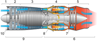
This article briefly describes the components and systems found in jet engines.

An airbreathing jet engine is a jet engine in which the exhaust gas which supplies jet propulsion is atmospheric air, which is taken in, compressed, heated, and expanded back to atmospheric pressure through a propelling nozzle. Compression may be provided by a gas turbine, as in the original turbojet and newer turbofan, or arise solely from the ram pressure of the vehicle's velocity, as with the ramjet and pulsejet.

Internal combustion engines come in a wide variety of types, but have certain family resemblances, and thus share many common types of components.

The Power Jets WU was a series of three very different experimental jet engines produced and tested by Frank Whittle and his small team in the late 1930s.

<span class="mw-page-title-main">Internal combustion engine</span> Engine in which the combustion of a fuel occurs with an oxidizer in a combustion chamber

An internal combustion engine is a heat engine in which the combustion of a fuel occurs with an oxidizer in a combustion chamber that is an integral part of the working fluid flow circuit. In an internal combustion engine, the expansion of the high-temperature and high-pressure gases produced by combustion applies direct force to some component of the engine. The force is typically applied to pistons, turbine blades, a rotor, or a nozzle. This force moves the component over a distance, transforming chemical energy into kinetic energy which is used to propel, move or power whatever the engine is attached to.

<span class="mw-page-title-main">Velox boiler</span>

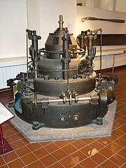
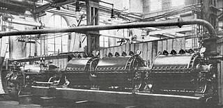
A Velox boiler is a turbocharged, forced circulation, water-tube boiler which utilises an axial flow compressor and a gas turbine. Velox boilers, also known as Velox steam generators, were developed in the early 1930s by the Brown Boveri Company (BBC) of Switzerland. Velox boilers were the first commercially available machines to make use of axial compressors and played a pivotal role in the later development of BBC’s industrial gas turbines.

<span class="mw-page-title-main">Pressure gain combustion</span>

Pressure gain combustion (PGC) is the unsteady state process used in gas turbines in which gas expansion caused by heat release is constrained. First developed in the early 20th century as one of the earliest gas turbine designs, the concept was mostly abandoned following the advent of isobaric jet engines in WWII.

<span class="mw-page-title-main">Armengaud-Lemale gas turbine</span> Early experimental gas turbine

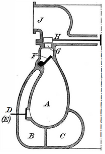
The Armengaud-Lemale gas turbine was an early experimental turbine engine built by the Société Anonyme des Turbomoteurs and exhibited during 1906 in Paris, France. The gas turbine could sustain its own air compression but was too inefficient to produce useful work. The Armengaud-Lemale combustion chamber design was later used successfully in torpedo engines.

References

  1. 1 2 3 4 5 Eckardt, Dietrich (2014). "3.3 - The Holzwarth Gas Turbine". Gas Turbine Powerhouse. Oldenbourg Verlag Munchen. pp. 72–76. ISBN   9783486735710.
  2. 1 2 3 Kay, Antony L (2002). "Holzwarth Gasturbinen GmbH". German Jet Engine and Gas Turbine Development 1930-1945. Airlife Publishing Ltd. pp. 193–194. ISBN   9781840372946.
  3. 1 2 3 Meyer, Adolf (1939). "The Combustion Gas Turbine, Its History, Development and Prospects". The Brown Boveri Review. 26. Baden, Switzerland: Brown Boveri and Company.
  4. 1 2 3 4 5 6 Noack, Walter G (1941). "Pressure Charging, Velox Boiler and Gas Turbine, a review of their origin and development by Brown Boveri" (PDF). The Brown Boveri Review. 28. Baden, Switzerland: Brown Boveri and Company.
  5. 1 2 3 Young, Steve (2019). "Who Invented Industrial Gas Turbines?". NEWSNOC. No. 19. Sharjah National Oil Corporation (SNOC). pp. 26–27.
  6. 1 2 3 "What Inventors Are Doing". Scientific American. 106 (24): 543–544. 15 June 1912.
  7. 1 2 Holzwarth, Hans (1912). "1 - General Description of the Gas Turbine Process". The Gas Turbine. London, UK: Charles Griffin and Company. pp. 1–2.